Although the exploitation of advanced composite materials in the aerospace industry is steadily increasing, high strength metallic materials, particularly aluminium alloys, are still the first choice for large-scale fleets such as the Airbus A320 and the Boeing 737. Since the introduction of stressed-skin “semi-monocoque” aircraft structures in the 1930’s the structural design philosophy has developed considerably, and the history of this development has been greatly influenced by in-service failures.
1930 – 1940: Early commercial transport aircraft. Design and structural design focus primarily on static strength with little regard to long- term material degradation by mechanical fatigue i.e. cracking, creep etc.
1940 – mid 1950’s: Aluminium alloys with higher static strength are developed to reduce material usage but with little improvements or even reductions in fatigue strength. A number of catastrophic in-service failures leads to the increasing awareness of fatigue failure for safe design.
mid 1950’s – present: The terms “fail-safe” and “damage tolerant” design are coined, which account for damaged and cracked structures before service. The embedded damage is expected grow during service as a result of cyclic loading. Safety is ensured by pre-service testing to ascertain the extent of damage that will induce ultimate failure, and regular inspection, repair and replacements in-service before the critical damage size is reached.
Four case studies are generally considered to be critical milestones in the development of current structural design for metallic aircraft structures (2-5).
Table 1. Four milestone aircraft failures that influenced future aircraft structural design (1)
year
aircraft failure
lessons learned
1954
Two DeHavilland Comet aircraft crash as a result of fuselage explosions
First indicator and seed for awareness of finite aircraft fatigue life as a critical design factor in modern thin-skinned aircraft shell structures. Development of full-scale fatigue testing.
1969
F-111 wing failure as a result of an undetected initial material flaw
Initial material flaws and defects have to be accounted for prior to service and monitored in-service. Aircraft should be damage tolerant.
1977
Boing 707 tailplane lost as a result of fatigue failure in a spar
The older the aircraft the more susceptible it is to fatigue cracking. Also crack growth accelerates with increasing size.
1988
Boeing 737 loses part of fuselage skin due to multiple fatigue cracks in spars
Multiple-site fatigue damage may occur in ageing aircraft. Joints in the structure are especially critical.
References
(1) R.J.H Wanhill (2002). Milestone Case Histories in Aircraft Structural Design. National Aerospace Laboratory. NLR-TP-2002-521
(2) J. Schijve (1994). Fatigue of aircraft materials and structures. Int. J. Fatigue. Vol. 16 (1) pp. 21-32
(3) T. Swift (1987). Damage tolerance in pressurised fuselages. 11th Plantema Memorial Lecture. New Materials and Fatigue Resistant Aircraft Design (ed. D L Simpson) pp 1 – 7. Engineering Materials Advisory Services Ltd., Warley, UK.
(4) A.J. McEvily (2002). Metal Failures: Mechanisms, Analysis, Prevention. Chapter 1. John Wiley & Sons, Inc. New York, USA
(5) A.F. Blom (2002) Fatigue science and engineering – achievements and challenges. 18th Plantema Memorial Lecture, ICAF’2001: Design for Durability in the Digital Age. Vol I, pp 3-64. Toulouse, France.
For many years engineers have been trying to harness mechanical work from thermal energy by taking advantage of the crystallographic phase change of shape memory alloys (SMAs). SMAs can exhibit strains of up to 8% actuated by a transformation of the internal crystal structure from martensite to austenite as the metal is heated. This solid state phase change causes a shearing of the internal structure that deforms the material. By introducing additional internal stresses the alloy can be “trained” to transition between two states by applying temperature changes. One of the most well-known projects of the past is the Smart Aircraft and Marine Propulsion System demonstration (SAMPSON), intending to demonstrate the potential of SMAs in tailoring the geometry of jet-propulsion systems through a series of experiments.
Boeing variable geometry chevron, flight testing (1)
One experiment investigated the utilisation of bending actuation of SMAs to optimise the compromise between noise-mitigation at take-off and landing (noise levels are strictly regulated by civil agencies), and maximum thrust at cruise altitude. To achieve this Boeing formed the trailing edge of the exhaust nozzles on commercial turbo-fat jet engines in a triangular “chevron” shape (Figure 1) designed to be reconfigurable by actuation of embedded SMA beam components. The “Variable Geometry Chevrons” (Figure 2) feature NiTi (60% Ni and 40% Ti by weight) SMA beam elements encased in the composite chevrons in a complex 3-D configuration to induce the necessary bending moments to force the chevrons inwards into the bypass flow at low altitudes and low speeds where the engine temperature is high. The intruding chevrons cause a disturbance in the bypass flow, inducing a broader diffusion and mixing of the hot exhaust gases with the cooler bypass flow. Thereby the shear stress between the two different-velocity flows is decreased leading to a reduction in the noise level.
FEA analysis of Boeing Variable Geometry Chevron with SMA strips shown (1)
At higher altitudes and high speeds where the engine temperature is low, the chevrons relax and straighten-out. This guarantees a smooth exit flow that decreases the pressure difference between the inlet and exit of the engine and thus increases the engine thrust. In the original work published by Mabe et al. (2005) the system is designed for both autonomous operation as well as controlled actuation using heaters installed in the engine casing with a closed loop controller to maintain optimum in-flight tip immersions. A parametric study showed that during cruise marginal immersion helped to reduce shock cell noise with negligible thrust penalty.
NASA developed an active bending chevron system by embedding tensile pre-stressed NiTinol SMA strips on one side of the neutral axis of the composite laminate. Actively controlled thermal excitation thus causes the SMA actuators to attempt recovery of the pre-strain constrained by the bond to the host material. The resulting asymmetry in thermal stress causes a moment that deflects the structure. The aerodynamic load due to engine flow and the strain energy stored in the deformed host composite are used to restore the structure to the un-actuated configuration.
The simple design appeals by its lightweight construction with low part count and opportunity to be fully integrated into an autonomous morphing system. The “Variable Geometry Chevron” demonstrates the excellent potential of SMA’s to be integrated in composite laminates to provide internal actuation for smart structures.
References
(1) DJ Hartl & DC Lagoudas (2007). Aerospace applications of shape memory alloys. Proc. IMechE Vol. 221 Part G: J. Aerospace Engineering
The exploitation of conventional, continuous fibre-reinforced plastics in engineering structures has been steadily diversifying from sports equipment and high performance racing cars, to helicopters and most recently commercial aeroplanes. The main benefits of composite materials, such as their excellent specific strength and stiffness properties, must be viewed with respect to in-plane fibre-direction applications. However, if a composite plate is subjected to significant out-of-plane stresses subsurface delaminations may develop between layers due to the weak through-thickness cohesive strength of the composite (2). Previously, techniques such as Z – pinning, stitching and 3D – braiding have been investigated to improve through-thickness properties but these tend to reduce the in-plane performance of the laminate by damaging primary fibres and inducing fibre waviness (1).
Carbon Nanotube interfacial strengthening
Throughout the last decade the huge interest in Carbon Nanotubes (CNT) has been fuel by their extraordinary intrinsic mechanical, electrical and thermal properties, which make them ideal candidates for multifunctional structures (3). To overcome the weakness of interlaminar strength considerable research has been conducted to develop hierarchical composite structures by using nanoscale CNT reinforcement alongside microscale carbon and glass fibers. Examples in nature such as cell walls and animal shells show that excellent mechanical properties can be obtained from spreading reinforcement over a number of length scales, even if the original constituents are fairly weak (4). This paper reviews the progress in developing such hierarchical composites to improve delamination resistance and through-thickness properties by intra- and interlaminar reinforcement of multiwall carbon nanotubes (MWCNT).
In an attempt to improve the through-thickness properties the introduction of CNTs should,
Ideally be attached radial to the primary fibres and extend into the surrounding matrix to stiffen the fibre/matrix interface, improve the primary fibre surface area and facilitate mechanical interlocking, all of which improves stress transfer.
Result in a uniform distribution of CNTs.
Not reduce the in-plane laminate properties.
Not introduce other secondary or additional modes of failure by damaging the primary fibres.
Allow a scalable, straightforward processing technique that can be easily incorporated with conventional manufacturing processes such as VARTM or pre-preg.
In the literature there are currently two popular methods to achieve this,
Dispersing CNTs in a polymer matrix followed by infusion of pre-forms with the CNT-reinforced resin,
A direct attachment of CNTs onto the external surface of the primary fibres subsequently infused with a pristine resin.
In the following sections the details of the two manufacturing approaches (shown schematically in Figure 1) are outlined and the implications of each approach on through-thickness performance such as interlaminar shear strength, and Mode I and Mode II critical fracture energy discussed.
Fig. 1. Schematic diagram of conventional CFRP and hierarchical CFRP with CNTs in matrix and grown on fibres (4).
CNT-reinforced Matrix
The simplest method to manufacture hierarchical nanocomposites is by mechanically or ultrasonically shear-mixing CNTs into low-viscosity thermosetting resins, and then infusing or impregnating the primary fibre stack using conventional techniques such as VARTM (5; 6; 7). To date the most uniform dispersion of MWCNTs throughout the matrix have been achieved by shear mixing using a three-roll mill (8; 9). On the other hand this approach is limited to short CNTs < 1 mm at low volume fractions of 1 – 2%, which greatly limits the reinforcement potential. Higher volume fractions are to date not possible since the viscosity of the matrix increases rapidly with CNT content leading to incomplete infusion (10) or CNT agglomeration/depletion in different areas of the fabric (11).
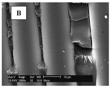
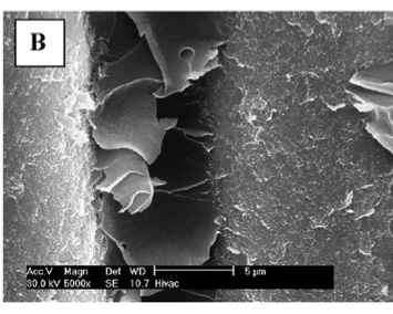
Flexural tests of hierarchical composites with glass and carbon primary fibres show that the in-plane stiffness and strength are not impaired by the MWCNTs (5; 8). Qiu et al. (5) actually showed an improvement in tensile strength and stiffness of a glass-fibre composite of 15.9% and 27.2% respectively, while Veedu et al. (12) showed improvements of 142% and 5% for carbon composites. Most importantly, short beam shear (SBS) and compression shear tests (CST) have shown increases in the matrix-dominated interlaminar shear strength (ILSS) between 8% and 33%. Scanning electron microscopy (SEM) images show that the MWCNTs in the resin lead to better fibre-to-matrix adhesion as well as pullout and rupture of the MWCNTs before final matrix failure, which consumes additional fracture energy (Figure 2).
Fig. 2a. Not reinforced
Fig. 2b. CNT reinforced
The SEM images also indicate that the alignment of the CNTs is heavily influenced by the direction of the resin flow during infusion and local orientation of the primary fibres (4). As resin infusion generally occurs in the through-thickness direction the VARTM approach can give some control in aligning the CNTs in the preferred direction for improving transverse properties, although a certain degree of random alignment remains. Furthermore, one study has shown (5) that functionalised MWCNTs resulted in slightly higher SBS shear modulus and strength (~3%) compared to a pristine un-functionalised MWCNTs. Using SEM imagery the authors showed that this stemmed from a superior interfacial bonding between the CNTs and the matrix.
Delamination resistance is generally investigated using Mode – I double cantilever beam (DCB) tests and Mode – II end-notched flexure (ENF) tests. The literature has shown (13; 14; 15; 16) significant improvements of up to 98% and 75% for Mode I and Mode II fracture toughness respectively compared to non-hierarchical composites. The characterisation of the fracture surfaces using SEM imagery has shown that the additional pullout and bridging of the CNT is responsible for the toughening. Similarly, Garcia et al. (13) have developed an efficient technique of growing CNT mats on growth substrates and then “transfer printing” the CNT mats in between tacky pre-preg plies using a roller. Since this process better controls the CNT alignment in the through-thickness direction much higher improvements of fracture toughness of 152% in Mode I and 214% in Mode II were observed. However, the process of “transfer printing” CNT films at every ply interface is a very time consuming endeavour and may therefore not be as applicable to scalable industrial integration as the VARTM process.
The fabrication of hierarchical composites by impregnating microscale primary fibres with nanoscale-modified resins is limited to maintaining low matrix viscosities. Furthermore, resin flow during impregnation tends to align CNTs parallel to the primary fibre direction, the least desirable orientation for improving through-thickness properties. In this respect growing or “grafting” CNTs directly onto the surfaces of primary fibres followed by infusion with a pristine, low-viscosity matrix allows higher volume fractions and is ideal for orientating fibres radial to the primary fibres. Furthermore, this approach overcomes the problems of CNT agglomeration or self-assembly into bundles as observed when CNT are freely dispersed in a matrix. Three techniques for attaching CNTs onto fibres were found to be most popular in the literature:
Direct growth of CNTs onto fibres via Chemical or Thermal Vapour Deposition (CVD and TVD) (12)
Electrophoretic deposition (EPD) (6)
Coating of primary fibres with CNT-modified sizing agents (7)
The first example of synthesising CNTs onto carbon fibres via CVD was conducted in 1991 by Downs and Baker (18). In this approach the primary glass or carbon fibres are initially oxidised with nitric acid and the iron catalysts then deposited onto the fibres using incipient wetness techniques such as sputtering, thermal evaporation or electrodeposition (4). The ultimate result is the growth of highly aligned and dense CNT forests onto fibre cloths (Figure 3) that are then stacked and impregnated by infusion techniques such as VARTM (12). Experiments have shown that the CNT forests are efficiently wet-out by liquid resins and polymer melts as a result of capillary forces (6; 19).
Fig. 3. SEM images showing CNT forests (b) grown in woven pristine fibre cloth (a) (12)
Recently, Injection CVD (ICVD) techniques have been favoured to then grow the CNTs on the primary fibres via a pyrolysis of solutions containing a catalyst precursor and a hydrocarbon source (20). The ICVD technique has resulted in better degree of orientation and growth of longer CNTs compared to classical CVD approach.
The most crucial parameters in grafting CNTs onto glass or carbon fibres are,
Choosing a good catalyst for strong anchoring interaction between CNTs and fibres to maximise stress transfer and reduce damage during manufacturing processes,
While
At the same time prevent oxidation damage to the primary fibres by to aggressive a catalyst.
Fig. 4. Electrophoresis (6)
Oxidation and gasification are especially problematic for carbon fibres since the active catalysts deposited onto the fibres etch into the surface and thus may reduce their strength by up to 55% (4). As a solution Bekyarova et al. (6) selectively deposited multi- and single-walled CNTs onto woven carbon fabric using electrophoresis. In this approach MWCNTs are first produced as is using a classical CVD process and then dispersed in an aqueous media between two negative electrodes to charge the CNTs (Figure 4). The dry carbon fabric was then immersed in the CNT doped media and sandwiched between two steel plates connected to a positive charge. Driven by the electric potential, the CNTs are thus deposited onto the carbon cloth and the CNT-carbon fibre performs then infused with epoxy using VARTM. A very simple approach has been presented by Zhu et al. (7) who sprayed nanotubes directly onto woven fibers prior to VARTM processing. The drawback of this technique compared with direct growth methods is relatively little control over the CNT orientation (4).
The pioneering work of Downs and Baker (21) reported a 4.75x increase in interfacial shear strength (IFSS) of a nanofibre-grafted carbon composite, although such incredible improvements have not been repeated thus far. Veedu et al. (12) showed improvements of 348% and 54% for GICand GIIC respectively for MWCNT enhanced SiC woven fabrics using a classical CVD technique; Bekyarova et al. have found improvements of 27% in ILSS for CNT enhanced carbon fabrics using electrophoresis deposition; while Zhu et al. demonstrated improvements of 45% in ILSS of MWNT doped glass fiber reinforced vinyl ester composites using a simple spray up with only 0.015 wt% of CNTs. In all three studies SEM imagery showed that the improvements arise from the increased surface area of the primary fibres and excellent wettability, which facilitates a strong bond between fibres and matrix by mechanical interlocking.
Based on these results the general consensus is that the damage tolerance of a structure can readily be improved by CNT grafting (4). However, there is also a large variability in the results arising from the different manufacturing processes, material combinations and CNT loadings applied that conceal the exact effectiveness of the method. There is agreement that the degree of enhancement is greatly dependent on the orientation and length of the grafted CNTs and further experimental research is required to ascertain the optimal morphology and manufacturing technique to achieve this (4).
Perspectives
The research so far has focused on demonstrating the great potential of CNTs to improve the through-thickness of properties of conventional FRPs. In the future research should focus on,
Developing scalable manufacturing processes that may find application in real, large-scale industrial applications.
Finding new approaches that solve agglomeration and high viscosity issues to allow higher loadings of CNTs.
Functionalisation of CNTs to improve CNT dispersion and stress transfer with the host matrix.
Reducing or preventing the reduction in strength of primary fibres induced by grafting fibres onto external surface.
Ascertaining the optimal CNT orientation and aspect ratio to optimise the through-thickness performance.
Key References
1. On the effect of stitching on Mode I delamination toughness of laminated composites. Lalit, Jain and Yiu-Wing, Mai. 1994, Composites Science and Technology, Vol. 51, pp. 331-345.
2. One Dimensional Modelling of Failure in Laminated Plates by Delamination Buckling. Chai, Herzl, Babcock, Charles and Knauss, Wolfgang. 11, s.l. : Pergamon Press Ltd., 1981, Int. J. Solids Structures, Vol. 17, pp. 1069-1083.
3. Big returns from small fibers: A review of polymer/carbon nanotube composites. Breuer, O and Sundararaj, Uttandaraman. 6, 2004, Polymer Composites, Vol. 25, pp. 630-645.
4. Carbon nanotube-based hierarchical composites: a review. Qian, Hui, et al. 2010, Journal of Materials Chemistry, Vol. 20, pp. 4751-4762.
5. Carbon nanotube integrated multifunctional multiscale composites. Qiu, Jingjing, et al. 2007, Nanotechnology, Vol. 18, pp. 1-11.
6. Multiscale Carbon Nanotube-Carbon Fiber Reinforcement for Advanced Epoxy Composites. Bekyarova, E., et al. 2007, Langmuir, Vol. 23, pp. 3970-3974.
7. Processing a glass fiber reinforced vinyl ester composite with nanotube enhancement of interlaminar shear strength. Zhu, Jiang, et al. 2007, Composites Science and Technology, Vol. 67, pp. 1509-1517.
8. Thostenson, E.T., Ziaee, S. and Chou, T.W. 2009, Compos. Sci. Techn., Vol. 69, pp. 801-804.
9. Seyhan, A.T., et al. 2007, Eur. Polym. J., Vol. 43, pp. 374-379.
10. Gojny, F.H., et al. 2005, Composites, Part A, Vol. 36, pp. 1525-1535.
11. Fan, Z.H. and Hsiao, K.T., Advani, S.G. 2004, Carbon, Vol. 42, pp. 871-876.
12. Multifunctional composites using reinforced laminae with carbon-nanotube forests. Veedu, Vinod, et al. 2006, Nature, Vol. 5, pp. 457-462.
13. Joining prepreg composite interfaces with aligned carbon nanotubes. Garcia, Enrique, Wardle, Brian and Hart, John. 2008, Composites: Part A, Vol. 39, pp. 1065-1070.
Bibliography (Further Reading)
14. Fan, Z.H., Santare, M.H. and Advani, S.G. 2008, Composites, Part A, Vol. 39, pp. 540-554.
15. Yokozeki, T., et al. Composites, Part A, Vol. 38, pp. 2121-2130.
16. Karapappas, P., et al. 2009, J. Compos. Mater., Vol. 43, pp. 977-985.
17. Godara, A., et al. 2009, Carbon, Vol. 47, pp. 2914-2923.
18. Downs, W.B. and Baker, R.T.K. 1991, Carbon, Vol. 29, pp. 1173-1179.
19. Qian, H., et al. 2010, Compos. Sci. Techn., Vol. 70, pp. 393-399.
20. Mathur, R.B., Chatterjee, S. and Singh, B.P. 2008, Compos. Sci. Techn., Vol. 68, pp. 1608-1615.
21. Downs, W.B. and Baker, R.T.K. 1995, J. Mater. Res., Vol. 10, pp. 625-633.
Laminar to Turbulent Transition in Cigarette Smoke
In another post I introduced the concept of skin-friction and pressure drag, and discussed the contradicting aerodynamic conditions to minimise either of the two types of drag. Overall the minimum resistance of slender shapes (such as aerofoils) to a fluid is attained with an attached laminar boundary layer over the entire surface. However, at some point from the leading edge the boundary layer will naturally transition to turbulent flow (see example of cigarette smoke), and any curvature in the shape will induce an adverse pressure gradient that can cause boundary layer separation. Consequently, laminar flow is generally restricted to a small percentage of the wing around the leading edge. For aircraft wings considerable research has been conducted to come up with mechanisms that maintain laminar flow over large parts of the wings and therefore reduce drag, fuel consumption and increase flying speeds.
One of the the first aircraft to attempt to take advantage of laminar flow was the WW II fighter P-51 Mustang. During the War the Americans and British developed a very slender aerofoil shape, now known as NACA 45-100, with the point of maximum thickness about half-way along the camber line in order to reduce the effects of the adverse pressure gradient. With the maximum camber in the middle it was thus possible to maintain a larger percentage of laminar flow over the wing. In 1938 wind-tunnel tests on the aerofoil recorded a drag coefficient of .003 which was about half of the lowest ever recorded for an aerofoil of similar thickness [1]. On the aircraft however the results of the controlled laboratory tests were never achieved. Laminar flow is a sensitive phenomenon and the slightest roughness of the aerofoil surface roduced by splattered insects, protruding rivets or imperfections in machining will cause premature transition to turbulent flow before the design condition. Furthermore, the air passing through the propeller produces a highly turbulent slipstream which is exacerbated by the vibration of the entire fuselage.
North American XP-51 Mustang
In order to improve on this early design NASA has conducted an array of flight tests on aircraft designed for natural laminar flow (NLF). To protect the leading edge from insect contamination one concept features wrapping the leading edge with paper during take-off, which is then torn-off at higher altitudes. A rather resource wasteful solution! Another solution using wire and felt pad scrapers, to as the name suggests, scrape dead insects from the surface of the wing. Furthermore, covering the leading edge with a curved deflector plate known as a Krüger nose-flap has been investigated on various aircraft. The drawback of these designs is that they disturb the streamlined profile of the aerofoil and therefore induces parasitic drag that outweighs the improvements of maintaining laminar flow. The Krüger flap concept is nowadays incorporated in high-lift devices but only used during landing and take-off, which only accounts for a fraction of the full flight time
Tests on an experimental F-16XL aircraft were used in a NASA programme to assess laminar flow on aircraft flying at supersonic speeds. The main aim was to assess the merit of swept-wings for future high speed civil aircraft. The swept delta-wings used active perforated titanium “gloves” attached to the surface featuring tiny holes through which most of the boundary layer was drained-off by an internal suction system. The panels covered 60% of the wing’s leading edge perforated with about 10 million microscopic size laser-cut holes. Through these holes the suction system in the wing drew away a significant portion of the slower fluid in the boundary layer close to the surface, thereby expanding the extent of laminar flow across the wing. The Supersonic Laminar Flow Control (SLFC) successfully achieved laminar flow over large portions of the wing up to supersonic speeds of Mach 1.6 [2].
The concept of using suction wings to maintain laminar boundary layers has thus far been the most researched and promising solution. Before these technologies can be applied issues such acceptable reliability, maintainability and operational characteristics have to be resolved and the long-term technical and economic viability of the technology demonstrated. The current legislative framework requires the development of novel aircraft design in the near future in order to meet the ambitious fuel economy requirements. Perhaps advances in micro-machining, nanotechnology and smart-material technologies will lead to LFC devices becoming integral parts of revolutionary new aircraft.
F-16XL fighter with suction panels
References
[1] http://yarchive.net/mil/laminar_flow.html
[2] R.D. Roslin (1998). Overview of Laminar Flow Control. NASA Technical Report. NASA Langley
In today’s time it is easy to take for granted the complex inventions that alleviate our everyday life. The modern jet propelled airplanes for example, are one of the biggest drivers behind rapid globalisation and play a major role in world trade. Nevertheless, the development that revolutionised aviation and inaugurated the era of jumbo jets came in a time of European and World conflict. It was at the dawn of World War II that two engineers from opposing sides of the war, separately and unaware of the other’s contribution, engineered the Jet Engine that would shrink the world in the 20th century and set the groundwork for other milestones in aviation such as supersonic flight and space exploration.
The notion of jet propulsion has been around for centuries. The concept of jet engines can actually be traced back to the first century AD, when Hero of Alexandria introduced the “aeolipile”. This machine used pressurised steam forced through two jet nozzles placed on the surface of a sphere so as to force the sphere to spin rapidly on its axis [1]. Jet propulsion got off to its “flying start” with the Chinese invention of the rocket used for fireworks in the 11th century. By the early 20th century jet propulsion was a known principle and viewed as a potential alternative to standard propeller engines, especially in high-speed flight. By the 1920s jet engines, powered by an external power source, were used to propel racing planes but proved to be inefficient for low-speed flight.
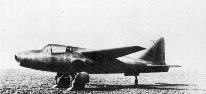
Heinkel He 178
On the German side of WWII a young German physicist, Hans von Ohain, was at the forefront of research into jet propulsion [2]. Hans von Ohain was born in Dessau on December 14, 1911 and received his Ph.D. in Physics and Aerodynamics from the University of Göttingen. During his studies he established the notion that one could build “an engine that did not require a propeller.“ Von Ohain’s first attempt to build a jet engine, which he patented in 1936, was not a great success. The jet engine had been built by an automotive engineer, Max Hahn, but ran into serious problems with combustion stability [3]. Most of the fuel would not ignite within the engine but would combust in the outside air. This caused flames to shoot out the back and prompt the electric motor powering the compressor to overheat. When Ernst Heinkel, one of the largest German aircraft manufacturers of the time, heard of von Ohain’s work he recognised the promise of the design and started to provide financial and technical funding [1]. After a two-month period of research on the airflow in the engine Max Hahn, von Ohain and Heinkel’s best engineers completed construction of a totally new engine that ran on hydrogen. As the high-temperature hydrogen exhaust damaged the metal framework, the old HeS 1 engine was refined to run on gasoline, a centrifugal compressor and axial turbine stages. This new engine, the HeS 3b, was then fitted to a new test airframe, the Heinkel He178. On August 27, 1939 the Heinkel He178 took off from Marienehe aerodrom and was thus the first jet-powered airplane. In 1940 the engine designer Anselm Franz developed the Jumo 004 engine with an axial-flow turbojet, as opposed to the centrifugal-flow designs [4] of the original von Ohain engines. This engine was used to propel the Messerschmitt Me262 in 1942, the only jet fighter airplane in WWII.
At about the same time in England Frank Whittle, born on June 1, 1907 in Earlsdon as the son of a mechanic, developed his version of the jet engine unaware of von Ohain’s achievements. In a 1928 in an astonishing student essay Future Developments in Aircraft Design Whittle showed that at increasing altitudes of flight the lower outside pressure and density of air would reduce drag with subsequent improvements in fuel efficiency and flight speed. In these conditions Whittle contemplated speeds of 600 mph at 60,000 feet when at the time the fastest RAF plane flew at 150 mph at a maximum altitude of 15,000 feet. However, current designs based on the internal combustion engine were being starved of oxygen at higher altitudes, which essentially limited current fighter planes to lower and slower flight conditions. Whittle therefore proposed a new form of propulsion – the jet engine.
Whittle Jet Engine W2-700
Whittle’s patent showing a centrifugal-flow engine with a multi-stage axial followed by a centrifugal compressor was granted in 1932. Unluckily Whittle was unable to excite either RAF nor the government to fund his work. Therefore he, Rolf-Dudley Williams and J. Tinling, two ex-RAF men who were interested in his work, incorporated the Power Jets Ltd. Even though the company only received minimal funding from outside investors, Power Jets were able to complete and run their first engine, the Whittle Unit, on April 12, 1937. This achievement triggered the interest of the Air Ministry, which now started to grant minimal amounts money in order to develop a flyable version. On May 15, 1941 the revised engine W.1 with 3.8 kN thrust and manufactured by Rover was fitted to the Gloster E.28/39 airframe and took off for a flight of about 17 minutes with a maximum speed of 545 km/h. Rolls-Royce then took over the development and production of the Whittle engine, which led to the Whittle-type Rolls-Royce Welland and the W.2 engines [5]. These new designs were used to propel the interceptor Gloster Meteor 1 in 1944.
After the war the British shared Whittle’s technology with the United States, enabling the engine-builder General Electric (GE) to build jet engines for America’s first jet fighter, the Bell XP-59. Another American jet engine designer Pratt & Whitney improved the fuel economy of jet engines, while a General Electric engineer named Gerhard Neumann introduced the variable stator; preventing jet engines from gulping in too much air and restraining them from losing all their thrust [5].
During the last 40 years jet engines have been improved in a variety of ways, and have also been combined or replaced with rocket engines. For example, manned superplanes like the rocket-powered X-15 can fly almost 7 times the speed of sound, while the new A380 can transport up to 800 passengers in a luxurious ambience. It is remarkable to say that the early steps taken by Whittle and von Ohain laid the foundation for all these new magnificent aircraft.
Diagram of a typical gas turbine jet engine. Air is compressed by the fan blades as it enters the engine, and it is mixed and burned with fuel in the combustion section. The hot exhaust gases provide forward thrust and turn the turbines which drive the compressor fan blades