As I described in a previous post, the efficiency of the gas turbine cycle increases as the turbine entry temperature (TET) is increased. Therefore the hotter the combustion gases that enter the first turbine stage the more specific power the jet engine can produce. Of course the TET is bounded by the metallurgical limits of the blade materials, specifically the blade root stress, the creep strain and the melting point of the blade material. The centrifugal stresses at the root increase linearly with the density of the blade material, and linearly with both the square of the rotational speed and the square of the ratio of root-to-tip radius. Creep is the continual and gradual extension of a material under constant load over time. Apart from distorting the physical dimensions and thereby reducing performance of the engine, the induced creep stresses exacerbate the centrifugal operating stresses and will therefore lead to premature failure of the material. A rule of thumb is that the blade life is halved (for a specific blade material and cooling technology) for each 10°C rise in temperature of the metal [1]. The TET has risen from about 1050K in 1944 to about 1750 in the 1994 Rolls-Royce Trent engine. This is partially due to the use of better materials such as Inconel and single-crystal metals with better creep and fatigue properties. However there is a bound to this solution since these nickel-based alloys are typically quite heavy, leading to an increase in centrifugal stresses at the root. Therefore more important in this development has been the technology of channelling of cold compressor air to cool the turbine blades. Using these advanced cooling techniques has allowed engineers to increase the TET beyond the melting point of the blade materials.
In a modern engine around 20% of the compressed air is bled off for cooling and sealing purposes for nozzle guide vanes and turbine blades [1]. This internal air system illustrated in Fig. 1 is also used to prevent the any hot mainstream gases from flowing over the heavily stressed blade-attachment discs and control tip clearances between turbine blades and casing. The stators and outer wall of the turbine flow passage use cooling air traveling from the compressor between the combustor and outer engine casing. The turbine rotor blades, disks and inner walls of the turbine flow passage use air bled from the compressor through inner passageways. Since the stators (or nozzle guide vanes) appear before the the first row of rotating blades, the first stage of stators are exposed to the highest temperatures, including local hot-spots from the combustor close by. The temperature at the first rotor stage is then somewhat decreased by dilution of the gases with cooling air, relative velocity effects and power extraction (by gas expansion causing a drop in temperature) from the turbine. In this manner the temperature reduces through each blade row.
Fig. 1. Detailed turbine cooling paths for stator and rotor stages [2]
The laws of thermodynamics require that due to combustion inefficiencies there be a pressure loss within the combustor. This means that the mainstream pressure at the first row of stators in the turbine directly after the combustor be lower than at the exit of the final stage of the compressor. It is this pressure difference that we use to drive the cooling air through the internal passageways and into the stators and blades. In this respect improvements in combustor design over the last years has been both an advantage and a disadvantage for cooling engineers. Improvements in combustor design has led to lower pressure losses within the compressor such that more force is available to drive the bled air to the hotter aft parts of the engine. On the other hand, with increasing compression ratios the air within the compressor naturally reaches higher exit temperatures (today around 900K !!! prior to combustion [1]) reducing the effect that the cooling air has on the turbine blades. Furthermore, the cooling air is expensive from an efficiency point of view since work has been done on the compressed fluid and we would ideally like to “waste” as little as possible for secondary cooling purposes. As in most case a compromise has to be struck between power output and turbine life.
Fig. 2. Evolution of turbine blade cooling technology [3]
Figure 2 illustrates the evolution of turbine blade cooling over the last decades. In the early days of the jet era convection cooling was extensively used where the rotating blade acts as a single-pass cross-flow heat exchanger. This means that the bled compressed air flows radially through cooling passages in one-direction from root to tip, driven by the pressure differences and centrifugal forces, thereby removing heat convected to the blade from mainstream gases from axially. Improvements in modern manufacturing technology means that it is now possible to create a serpentine labyrinth of cooling passages within the blade turning the system into a multi-pass heat exchanger with higher cooling capabilities. Typically these passageways also have internal ribs and fins to increase the internal whetted area available for cooling. Furthermore, the cooling air is also vented through tiny holes onto the blade aerofoil surface, especially near the leading edge. In the ideal case the cooling air emerges at low velocity, forming a protective cooling film around the blade, hence the name film cooling.
The general cooling principles outlined above can be extended and combined to different cooling techniques. Some research has been conducted on exotic techniques for turbine discs as using pre-swirl nozzles to swirl the cooling air in the direction of the rotating discs. The increase in kinetic energy reduces the effective temperature of the air when it enters the cooling ducts in the blades. However the flow and heat structures that arise in these systems give rise to complex centripetal and Coriolis accelerations leading to accelerations in excess of 10,000g ! [1] with cyclonic and anti-cyclonic currents that are very difficult to model accurately.
The turbine is at the heart of any jet engine with its primary task being to drive the compressor. As described previously without the compressor no mechanical work would be done on the fluid prior combustion and the thrust produced would only be a function of the chemical energy stored within the fuel. The hot combustion gases that enter the turbine directly after the combustion chamber are expanded across a series of vanes and stators, known as a stage, similar to the compressor. In the case of a turbine the fluid is expanded to extract useful work and therefore the pressure of the fluid falls across each turbine stage. Since the fluid is not working against an adverse (rising) pressure gradient boundary layer separation over the aerofoils of the turbine blades is not as critical such that turbine blades can have much more agressive angles of attack with respect to the flow. Consequently, the pressure ratio across a turbine stage can be much higher than across a compressor stage and it quite common for a single turbine stage to drive six or seven compressor stages. The amount of power that can be extracted from a turbine stage is tremendous and a single turbine blade (not the full rotor of blades) may contribute up to 250 bhp [1]. The biggest driver behind the progress in turbine technology since Whittle’s first engine in the 1930’s has been the development of advanced cooling methods and the use of high-temperature alloys.
Similar to compressors axial turbines seen on most modern jet airliners are more efficient than their radial counterparts at higher flow rates. However, radial turbines are still being used on modern aircraft for auxiliary power units. Figure 1 below shows a single-shaft three-stage axial turbine i.e. the three turbine stages drive all of the compressor stages through a single shaft.
Fig. 1. Triple Stage Turbine [2]
The hot gases that exist the combustion chamber and impinge on the first row of nozzle guide vanes that turn the flow into the rotating turbine blades at the optimal angle to extract the most amount of work. Each stage of vanes and blades expands the flow thereby resulting in a drop in enthalpy (total amount of energy in the combustion gases) and a transfer of work from the fluid to the turbine. For simple jet engines the overall performance of the engine is more effectively enhanced by developing the compressor stages. However for large by-pass turbofan engines turbine aerodynamic design is crucial. Figure 2 shows the velocity triangles for the flow passing through a single turbine stage. Separate turbine rows are typically placed very close together, around 20% of a blade chord [1], and the tangential velocity of the rotor blades ( is the rotational speed and the radius of the blades) is close to the local speed of sound.
Fig. 2. Velocity triangles for turbine stage [2]
The main function of the stator is not to do work but to add swirl to the flow into order to convert some of its internal heat into kinetic energy. The turbine rotor then extracts work from the flow by removing the kinetic energy associated with the swirl velocity. In the global reference frame of the engine the flow into the stator and rotor is highly unsteady and of great complexity. However, in a frame of reference fixed to a rotating blade it can be assumed to be fairly steady with sufficient accuracy. For the first row of stators (or nozzle guide vanes) the flow impinges parallel to the axial flow direction and is consequently turned through angle with respect to the axial direction by the stator. Thus the flow leaves the stator at with a velocity with respect to the stator which is equivalent to a velocity at an angle with respect to the rotating blade. At optimum design condition is equal to the angle of rotor blade. and are the relative exit speed and blade angle respectively, such that the turning angle is equal to . An important design parameter for turbine performance is the blade coefficient , which is the ratio of the total temperature drop (which is proportional to the work done) across a stage divided by the kinetic energy of the rotor.
High efficiency are achieved with lower temperature drops per stage and therefore smaller values of and lower turning angles . However large values of are required to reduce the number of stages and keep the weight of the engine down. Consequently a compromise has to be struck between optimising thermodynamic efficiency and weight.
If the high pressure of the fluid exiting the combustion chamber were expanded in a single stage a very high velocity close to 1500 m/s [1] would be produced, which due to losses associated with supersonic shock waves, would be impossible to use efficiently. Therefore the turbine stages make a series of incremental expansions resulting in flows just over the local speed of sound, which, as shown by the velocity triangles, is apparently reduced on entry to the next stage as a result of the change in reference frame. Thus the velocity triangles show that the velocity leaving the stator is high in the frame of reference appropriate to the stator but much lower when seen at the rotor entry . Similarly the velocity leaving the rotor is high in its relative frame of reference . but lower in the absolute frame appropriate to the stator . Thus each of the turbine rows takes in a flow which is almost axial down the engine and turns it towards the tangential thereby reducing the effective cross-sectional flow area, which, by conservation of momentum, must result in an increase in fluid velocity.
Turbine Stresses
The turbine inlet blades of the first stage are the most likely to determine the life of the engine since they are exerted to the highest fluid temperatures, highest rotational speeds and highest aerodynamic loads. Stresses in the rotor blades also place restrictions on the allowable blade heights and annulus flow area. The gross of the mechanical stresses arise from the centrifugal stresses of the rotating turbine and bending moments exerted by the flowing gases, which unfortunately are both maximum at the blade root. The problem of centrifugal root stress was previously discussed for compressor blades. The turbine blades are of course tuned such that none of its natural frequencies coincide with any rotational or fluid excitation frequencies so as to prevent resonant behaviour. The gas turbine produces higher specific power and thus efficiency as the turbine entry temperature (TET) of the gas exiting the combustion chamber is increased. Of course the TET is bounded by the metallurgy of the turbine blade materials. The TET has increased from around 800°C in 1940 to 1500°C in the 1994 Rolls-Royce Trent engine. This development has in part been due to better materials but more importantly through channelling of cold compressor air to cool the turbine blades.
In this high temperature environment the life of the turbine blades is limited by creep, which is the continual and gradual extension of a material under constant load over time. Apart from distorting the physical dimensions and thereby reducing performance of the engine, the induced creep stresses exacerbate the centrifugal operating stresses and will therefore lead to premature failure of the material. Under ambient temperature creep is often only a factor for elastomers and other plastics, but at higher temperatures the effects become increasingly more pronounced for metals as well. A rule of thumb is that the blade life is halved (for a specific blade material and cooling technology) for each 10°C rise in temperature of the metal [1]. In the early days of turbine technology blades were forged but later cast for better high temperature performance. It was then found that by elongating the metal crystals along the direction of the span, creating so called directionally solidified blades, resulted in further improvements in creep performance. The standard technique for high-performance blades is to cast the blade out of a single crystal as shown in Figure 3 below. Metals may deform by separate crystals slipping along grain boundaries, such that removing the grain boundaries all together results in great improvements in resisting creep deformation.
Fig. 3. The microstructure of the three different turbine blades [4].
A typical alloy used for turbine blades today is Inconel, a nickel-based alloying containing 13% chromium, 6% iron, with small amounts of manganese, silicon and copper. These metallurgical advances account for some of the improvements in driving up TET and turbine efficiency. The other very interesting and complicated technology are blade-cooling techniques. But that is a topic for another article all together.
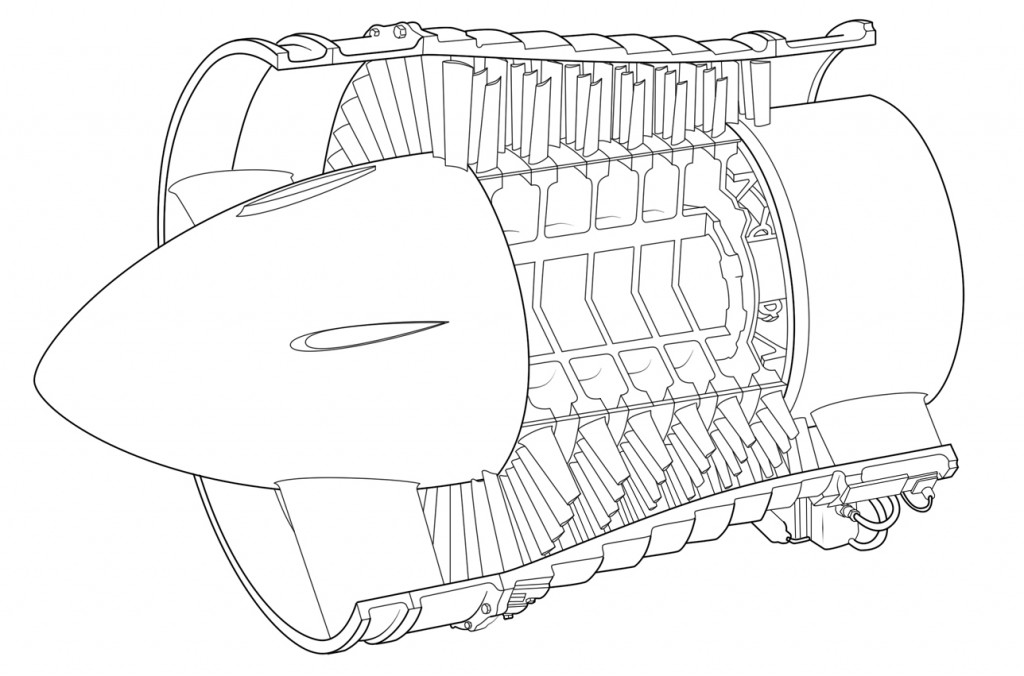
In this post the design of jet engine compressors will be discussed leading to the definition of ballpark performance parameters. For smaller engines centrifugal (CF) compressors are used since they can handle smaller flow rates more effectively and are more compact than axial compressors. Axial compressors however have the advantage of a smaller frontal area for a given flow rate, can handle higher flow rates and generally have higher efficiencies than CF compressors. For larger turbines used on civil aircraft the most suitable compressor and turbine will be of the axial type. Early axial compressors were able to raise the pressure of the incoming area around 5-fold, while modern turbofan engines have pressure ratios in excess of 30:1.
Low pressure axial compressor scheme of the Olympus BOl.1 turbojet
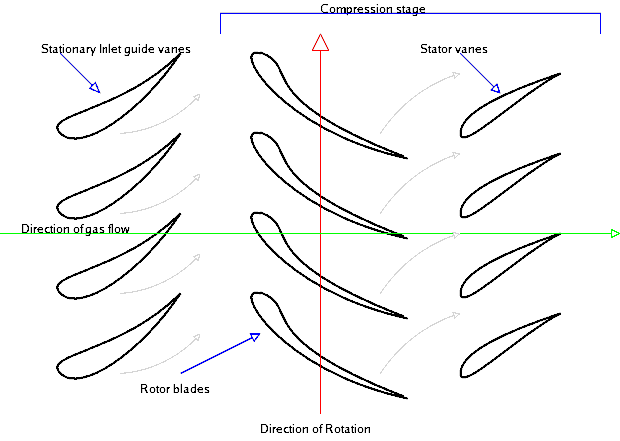
Because the pressure rises in the direction of flow through the compressor there is an acute risk of the boundary layers separating on the compressor blades as they encounter this adverse pressure gradient. When this happens the performance of the compressor drops dramatically and compressor is said to stall. For this reason the compression is spread over a large number of compressor stages such that the smaller incremental increases in pressure across each stage allow engineers to obtain a large overall pressure ratio without incurring stall. A stage consists of a row of rotating blades called the rotor and a row of stationary blades called the stator. Each of these rows may consist of between 30–100 distinct blades and there may be up to 20 stages between the air inlet and compressor outlet. The role of the rotor blades is to accelerate the incoming air in order to increase the kinetic energy of the fluid. Across the stators the fluid is then decelerated and as a consequence the fluid pressure is increased. As the pressure and density increase across each stage the overall flow velocity is kept relatively constant by reducing the height of the blades from stage to stage. Thus the compressor tapers down from inlet to outlet.
In an attempt to reduce the number of compressor stages for a more compact engine, a designer’s goal is to maximise the pressure ratio across each stage. The stage pressure ratio is given by the following expression,
Where is the stage isentropic efficiency, is the total (stagnation) temperature, the rotary speed of the compressor, the axial speed of the fluid, the coefficient of latent fusion at constant pressure, and and the angle of the rotor blade leading and trailing edge relative to the axial flow direction.
Diagram of an axial flow compressor
The pressure ratio across each stage can be maximised by increasing the rotary speed of the compressor , the angle through which the fluid is turned across the rotor blades and the axial speed of the fluid through the compressor. However there is a limit on the extent of these three parameters.
1. The blade tip speed and therefore is limited by stress considerations at the root. If the fan is assumed to be of constant cross-sectional area then the centrifugal stress at the root is given by,
Where is the tip speed, is the density of the blade, and the ratio is called the root-to-tip ratio of the blade. To prevent the blades from detaching from the hub and destroying the engine this root stress is not allowed to exceed a certain proof stress. It can be seen that the root stress is proportional to the square of the compressor rotational velocity and decreases as the blade length becomes shorter. Since the first compressor blades have the highest blade lengths they limit the maximum tip speed and therefore the efficiency of the compressor. It is therefore common to split the compressor into double or triple spool configurations such as a large fan, intermediate-pressure and high-pressure compressors that are rotating at three different speeds. In this manner the large diameter fan can rotate at lower speeds to satisfy the stress restrictions while the shorter blade high-pressure compressor may rotate at higher speeds.
However the rotational speed of the fan is typically constrained by more stringent stress considerations. In a turbofan engine the large diameter fan at the front of the engine acts as a single-stage compressor. In modern turbofan engines the fan divides the flow with most of the air going to the bypass duct to a propelling nozzle and only a small portion going into the core. The high root stresses caused by the long fan blades are often exacerbated by bird strikes. For mechanical reasons a lower limit of root-to-tip ratio of 0.35 is often employed. The flow impinging onto the fan is also at a very high Mach number since the cruising speed of civil aircraft is typically around M = 0.83. Supersonic flow inevitably terminates in a shock wave with a resulting increase in pressure and entropy over the compressor blades. Shock waves reduce the efficiency of the compressor blades since they disturb the flow over the profile that lead to boundary layer separation. Furthermore, these shock waves may cause unwanted vibrations of the fan blades that further reduce the efficiency of the compressor and increase noise. Therefore for reasons of efficiency, reducing noise and limiting the damage of bird strikes the tip speed of the fan is restricted, typically a relative Mach number of 1.6 is considered as the upper limit.
2. The axial speed has to be maximised to optimise the pressure ratio and reduce the frontal area of the engine. Similar to the argument given above the axial speed is typically limited by compressibility effects of supersonic flow. As the pressure, static temperature and therefore the speed of sound increases from stage to stage, the compressibility effects are worst in the first stages. For the first stage the air enters axially such that by adding the orthogonal velocity vectors and we get where V is the speed relative to the blade. In modern engines may be in the transonic region incurring quite large losses. In this respect twin-spool engines have the advantage that the lower-pressure compressor rotates at a lower speed, which reduces the compressibility problem.
3. The angle through which the fluid is turned across the rotor blades b is limited by the growth of the boundary layers. Compressor blades are aerofoils that function in the same manner as aeroplane wings. Therefore as the angle of attack or camber of aerofoil is increased to increase the rotation of the flow velocity vector, the adverse pressure gradient across the suction surface increases, until at some point the boundary layer separates. As the boundary layer separates the effective turning angle b is reduced such that the total pressure increase across the stage reduces.
The limits of , and all place limits on the maximum pressure ratio that can be achieved in an axial compressor. Typical examples are 350 m/s, = 200 m/s, 45°.
Compressor blades are typically quite thin and are constructed from lightweight metallic alloys such as aluminium and titanium. The compressor blades feature an aerofoil section as shown in the Figure below. The centrifugal forces that act on the airflow are balanced by high-pressure air towards the tip of the blade. In order to obtain this higher pressure towards the tip the blade must be twisted from root to tip in order to change the angle of incidence on the flow, and therefore control the pressure variation over the blade.
For aircraft jet propulsion there are in general four distinct designs: the turbojet, turbofan (or bypass engine), turboprop and turboshaft. This post will address the layout and design of the two most common engines used in modern aircraft, the turbojet and turbofan, and explain how their characteristics make each engine applicable for a specific task. Specifically, two important topics are addressed. The first is the multi-shaft engine with separate low-pressure and high-pressure spools and the second is the bypass engine, in which most of the air compressed by a fan bypasses the core combustor and turbine of the engine.
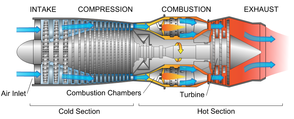
In general each engine is made up of four essential components: the compressor, combustor, turbine and nozzle as shown in Figure 1. The compressor raises the pressure of the incoming air before combustion, and the turbine, which extracts work from the hot pressurised combustion products, are at the heart of the engine. The role of the power turbine is not to provide thrust but to drive the compressor. The hot pressurised combustion products are expanded through a nozzle to produce thrust. In some military turbojet engines the exhaust velocity and therefore the thrust may be increased by “afterburning” in the exhaust duct.
Figure 1. Diagram of a typical gas turbine jet engine. Air is compressed by the fan blades as it enters the engine, and it is mixed and burned with fuel in the combustion section. The hot exhaust gases provide forward thrust and turn the turbines which drive the compressor fan blades.
1.1 The Turbojet
The turbojet is the earliest form of the jet engine as developed by Sir Frank Whittle and Hans von Ohain during WWII. It is no longer used for civil aircraft but predominantly used for high-velocity propulsion in military aircraft. Figure 1 shows a cross-sectional drawing of a typical turbojet engine and illustrates the typical layout of a turbojet engine with an axial compressor driven by an axial turbine, all on the same shaft. This assembly of shaft, compressor and turbine is oftentimes referred to as a “spool”. Newer engines typically have two or three spools such that the compression and expansion process in the compressor and turbine are spread over different parts. In this manner a low-pressure (LP) compressor and LP turbine are mounted on one shaft to form the LP spool. The LP shaft passes through the inside of the hollow high-pressure (HP) shaft on which are mounted the HP compressor and HP turbine. The compressor and turbine are split into separate parts to reduce centrifugal stresses in the compressor and turbine blades, and allow different parts of the compressor and turbine to be run at different speeds in order to optimise the running efficiency.
For sustained supersonic speeds a turbojet engine remains and attractive option for aircraft propulsion. The Rolls-Royce Olympus 593 is a two-shaft example that was used to propel the Concorde to twice the speed of sound.
1.2 A Note on Efficiency:
The propulsive or Froude efficiency of a jet engine is defined by the power output divided by the rate of change of kinetic energy of the air. The kinetic energy of the air represents the power input to the system. The power output is the product of force output i.e. the thrust and the resulting air speed . Although this is an approximation this equation summarises the essential terms that define aircraft propulsion. The force required to accelerate the fluid is given by the momentum equation,
Where is the mass flow rate of the air through the engine, is the velocity of the air entering and the velocity of the air leaving the engine. Thus there will be an equal and opposite force acting on the engine called the net thrust. The term is called the gross momentum thrust and is called the ram drag. Thus, for a turbojet the power output is,
So that,
For a fixed airspeed , can be increased by reducing . However decreasing decreases the thrust unless is increased. Thus, for civil aircraft when the economy is important is increased using high by-pass ratios of the turbofan, while for military engine where thrust is important low-by pass engines with large exit velocities are employed.
1.3 Optimisation of the Turbojet
When optimising the jet engine performance two parameters are typically considered: the specific thrust (ST) of the engine, and specific fuel consumption (SFC), the mass flow rate of fuel required to produce a unit of thrust. Generally speaking turbine designer have two thermodynamic variables to optimise these two entities: the compressor pressure ratio (R) and the turbine inlet temperature (TET). The effects of these two variables on SFC and ST will be considered in turn.
ST is strongly dependent on TET and TET should be maximised in order to keep the engine as small as possible for a specific amount of thrust. However, an increase in TET will incur a larger SFC at a constant R. On the other hand a gain in ST is generally more important than the penalty of higher SFC, especially at high flight speeds where a small engine is critical to minimise weight and drag.
Increasing R always causes a reduction in SFC and hence ensuring efficient compression stages is critical for an economic engine. For a fixed value of TET increasing R will initially result in more ST but will eventually cause ST to decrease again. Thus, there exists an optimum value of R, which is the role of the engineer to ascertain. Furthermore, the optimum pressure ratio for maximum ST increases with increasing TET.
This optimisation of R and TET can of course not be separated from the mechanical design of the engine. Driving up TET requires the use of much more expensive alloys and cooled turbine blades, which invariably lead to an increase in cost, mechanical complexity or otherwise a reduction in engine life. Increasing R will require larger compressors and turbines that incur weight, cost and mechanical complexity penalties.
Finally for different flight speeds and flight altitudes the performance of the turbojet will vary since the mass flow rate and momentum drag vary with density of the air and forward speed. Gross thrust decreases considerably with increasing altitude due to the decreasing ambient density and pressure, but specific thrust may increase due to a lower engine intake temperature. SFC however is reduced for increasing altitude, a result that was calculated by Frank Whittle as an engineering student, and led to his motivation for developing the jet engine.
2.1 The Turbofan
As revealed above the high exit velocity of turbojet engines does not allow high propulsive efficiencies required for civil aircraft. To raise the propulsive efficiency a bypass engine, often known as a turbofan engine, is used.
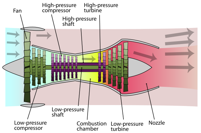
The core of the turbofan engine is essentially the same as the turbojet featuring a compressor, combustion chamber and power turbine as shown in Figure 2. However the engine features a second turbine that drives a large fan at the front of the engine. This fan delivers air to a bypass duct that channels air to the exhaust nozzle without passing through a combustion chamber. For this reason designers often refer to the cold flow in the bypass duct and hot flow through the core. Mixing the colder bypass air with the hot exhaust gases from the core results in higher propulsive efficiencies and lower noise levels. Early bypass engines typically had bypass ratios (the mass flow rate of bypass air divided by the mass flow rate of air going through the core) of around 0.3 to 1.5. The arrangements for modern airliners are High-Bypass-Ratio (HBR) engines with a bypass ratio of 5 or even more. In the Rolls Royce RB211 and Trent families the fan is driven at low speed by one turbine, and two internal compressors driven by another two separate turbines to give a triple spool engine.
Figure 2. Schematic Diagram of Turbofan Engine
2.2 Optimisation of the Turbofan
For turbofan design engineers have four major variables to consider: the bypass ratio (BR), overall pressure ratio (OR), fan pressure ratio (FR) and TET. Similar to the turbojet high TET is required for increased thrust. As the FR is increased the thrust contributed by the cold flow is increased while that of the hot flow decreases since more power is required to drive the fan. There is an optimum value of FR for which the total thrust is a maximum. In actual fact the optimum value of FR when is a maximum automatically produces minimum SFC if OR and BR are fixed.
The propulsive efficiency rises and the SFC falls as BR is increased. For laung-haul subsonic aircraft SFC is important to reduce cost. For these engines BR is typically between 4 and 6 and OP and TET are high. Thrust is more important for military aircraft such that BR is typically reduced to 0.5 to 1. BR significantly affects the engine efficiency, appearance, size and weight of the engine. As the weight of the engine increases less payload can be added to the aircraft such that the airlines revenue falls. Second, increasing the lift produced by the wings to carry bigger engines automatically induces more drag. Finally, for practical reasons BR > 10 are not practical with current technology since it would be necessary to install a gear box between the driving power turbine and fan to allow the turbine to run faster. Such a design would most certainly require considerable development time and would probably incur a weight penalty that outweighs the benefits of increasing the BR. Thus optimisation of the engine cannot only be considered in terms of thermodynamic parameters and aircraft manufacturers ultimately decide which engine to install based on what design gives airlines the highest financial yield.
In a typical turbofan jet engine the oncoming airflow is compressed throughout a series of compressor stages, mixed with a fuel (typically kerosene) and combusted, drastically increasing pressure and temperature, and then expanded through a nozzle to provide thrust towards the rear of the aircraft. By accelerating the fluid towards aft, Newton’s Third Law implies that this impulse must be reacted by an equal and opposite force in the opposite direction, thus propelling the aircraft forward. However, modern jet engines are also capable of producing thrust in the opposing direction. How is this possible without completely changing the direction of airflow from the exhaust to the intake which would seriously damage various engine components?
Diagram of a typical gas turbine jet engine. Air is compressed by the fan blades as it enters the engine, and it is mixed and burned with fuel in the combustion section. The hot exhaust gases provide forward thrust and turn the turbines which drive the compressor fan blades.
Thrust reversal is achieved by momentarily diverting the hot exhaust gases towards the front of the aircraft or changing the propeller/compressor pitch so that the thrust produced is directed forward. Thus thrust will act against the forward direction of travel and provide a means of deceleration. Thrust reversal is used in some flight scenarios in order to,
Alleviate the stress and reduce wear on the brakes or to enable shorter landing distances. Reverse thrust can reduce the braking distance by a third or more!
Momentarily increase the braking force during emergencies or just after touchdown when the aircraft is still traveling at a high velocity and the residual aerodynamic lift is significant. Lift reduces the normal reaction force with the ground and therefore limits friction and grip on the tyres.
Rapid deceleration in flight to enable quick changes of speed. Most aircraft cannot operate thrust reversal in flight and the majority that can are propeller-driven.
Helping to push an aircraft back from a gate. A maneuver called “powerback”.
Almost everyone who has sat in a row near the wings will have heard reverse thrust in action before. Next time you land wait for the sudden high-pitched increase in engine noise just after touchdown.
The method to achieve thrust reversal varies greatly between the different types of engines:
Since the 1930s propeller-driven aircraft generate reverse thrust by changing the angle of attack of their controllable pitch propellers:
Older reciprocating engines and modern turboprop engines both have the ability to set the propeller angle to “flat pitch”. As a result the propellor airfoils produce no forward or reverse thrust, but large amounts of drag instead. This allows the engine speed to be kept at a constant speed while descending.
The classic approach is to pitch the propeller blades to a negative angle of attack in order to direct the thrust forward.
In jet engines thrust reversal is not accomplished by running the engine in reverse but by diverting the high-velocity exhaust jet blast to the front of the engines. This can be achieved in different ways:
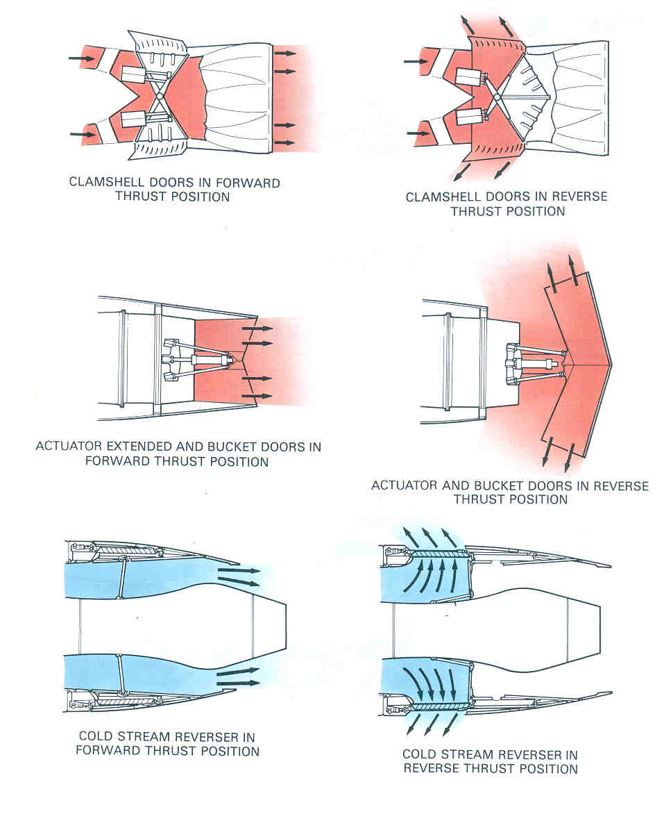
The target-type thrust reverser: After the combustion chamber, reverser blades angle outward in order to prematurely redirect the high-speed jet radially outwards and towards the front of the engine. This construction generally gives the appearance of flower petals.
The clamshell type: Two reverser buckets are hinged at the aft of the engine, and when deployed, intrude into the exhaust of the engine. In this manner the jet blast is captured and re-oriented towards the front.
In a turbofan engine some of the air intake is not passed through the main part of the engine, but redirected along an outside channel without being combusted. This bypass duct is aptly named “cold flow” and this arrangement is used to save fuel and reduce engine noise. Furthermore, the bypass flow can also be used to channel air radially outwards and forwards to provide thrust reversal.
The three different types of thrust mechanisms explained above [1].
Youtube has some great videos showing thrust reversal in action.
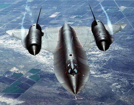
Aircraft have changed enormously over the last century from the early Wright Flyer flown at Kittyhawk to the supersonic SR-71 Blackbird flown today. Of course the developments in aeronautical engineering can be broken down into separate divisions that have developed at different rates: a) the aerodynamics, b) power plant engineering, c) control, radios and navigation aids, d) airframe engineering (e.g. hydraulic/electrical systems, interior fittings etc.), and finally e) the structural design. For example, power plants have developed in two large steps separated by a series of sudden burst of ingenuity. In order to facilitate the first successful flight the Wright Brothers had to find a light yet powerful engine system. The next stride was the ingenious invention of the jet engine prior and during WWII by Sir Frank Whittle and Hans von Ohain. In between, the power output of piston engines “increased almost 200 times from 12 bhp to over 2000 bhp in just 40 years, with only a ten times increase in mass (3) “. As will be outlined in this article, the design of aerospace structures on the other hand has only made one fundamental stride forward, but this change was sufficient to change the complete design principle of modern aircraft. Today however, the strict environmental legislation and advent of the composite era may induce further leaps in structural design.
Fig. 1. A schematic drawing of the Wright Flyer (1)
Fig. 2. The modern supersonic SR-71 Blackbird (2)
1) Wire Braced Structures
If we look at the early design of aircraft such as the Wright Flyer in Figure 1 there can really be no misunderstanding of the construction style. The entire aircraft, including most notably the wings, forward and rear structures were all constructed from rectangular frames that were prevented from shearing (forming a parallelogram) or collapsing by diagonally stretched wire. There were two major innovative thoughts behind this design philosophy. Firstly, the idea that two parallel wings would facilitate a lighter yet stronger structure than a single wing, and secondly, that these two wings could be supported with two light wires rather than with a single, thicker wooden member. The structural advantage of the biplane construction is that the two wings, vertical struts and wires form a deep light beam, which is more resistant to bending and twisting than a single wing. Much like a composite sandwich beam it can be treated as two stiff outer skins for high bending rigidity connected by a lightweight “core” to provide resistance to shear and torsion.
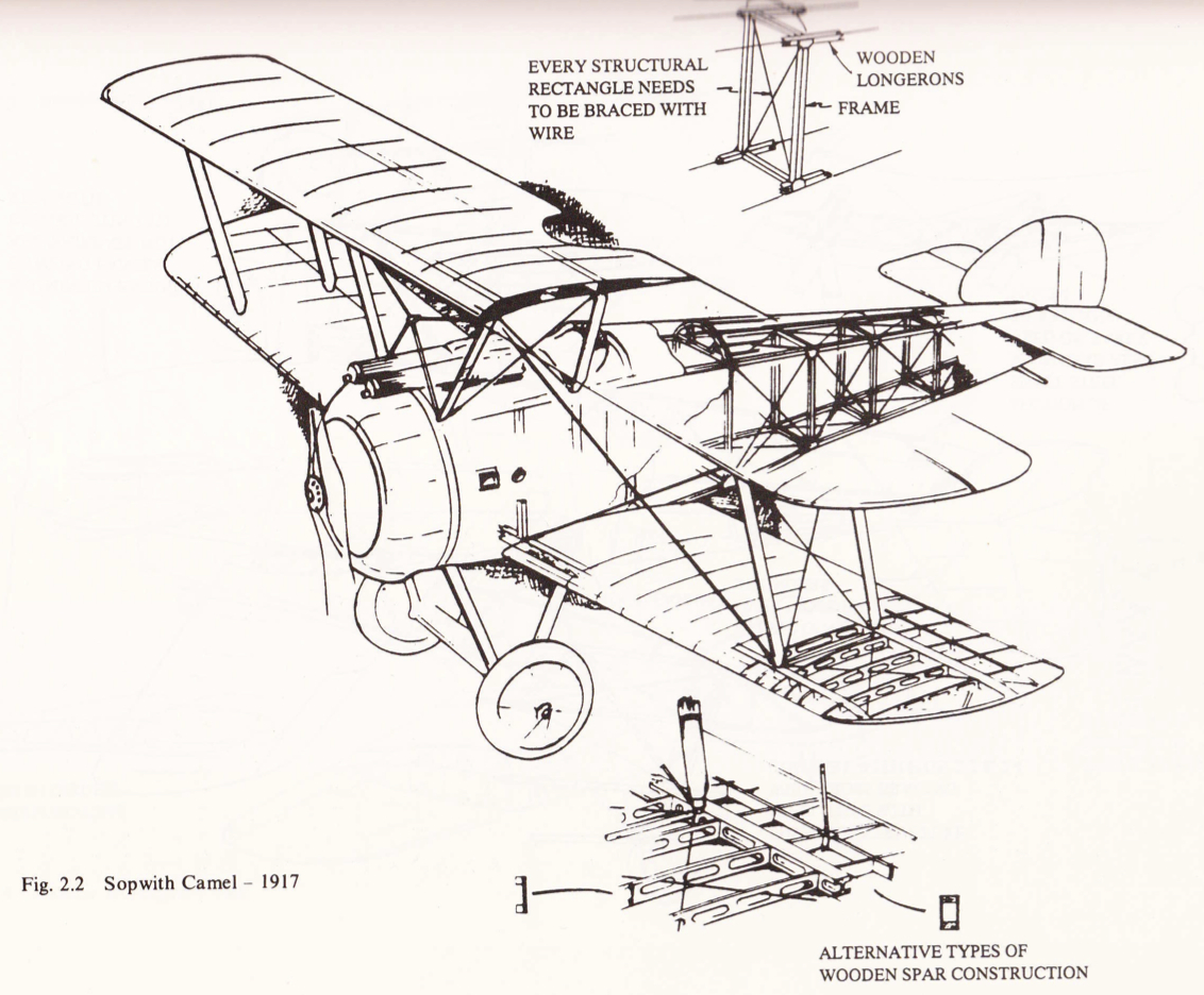
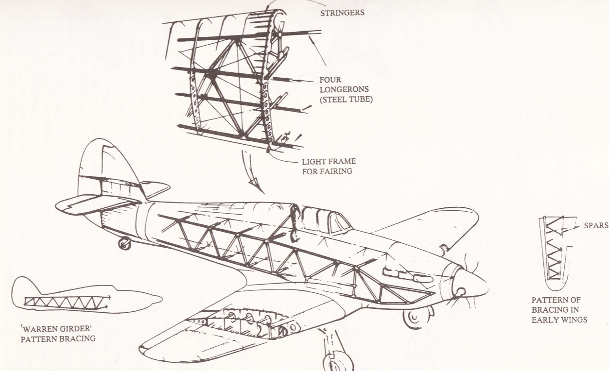
Fig. 3. Cutaway drawing of the 1917 Sopwith Camel (3)
Fig. 4. Cutaway drawing of the 1935 Hawker Hurricane (3)
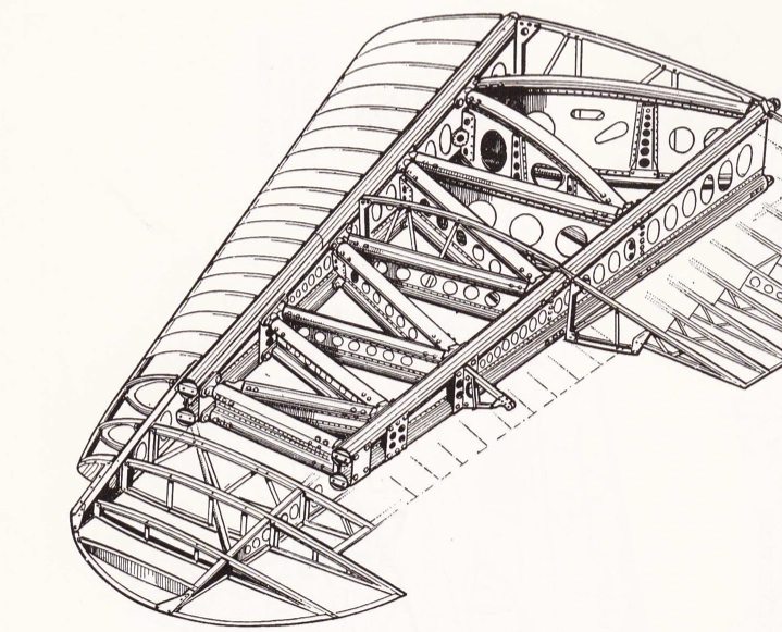
The biplane construction with wire bracing was the most notable feature of aircraft construction for much of the following years and paired nicely with lightweight materials such as bamboo and spruce (Figure 3). Wood is a composite of cellulose fibres embedded in a matrix of lignin and the early aeronautical engineers knew to take advantage of its high specific strength and stiffness. Strangely enough, after the era of metals we are now returning back to the composite roots of aircraft, albeit in a more advanced fashion. The biplane era lasted until the 1930s at which point metal was taking over as the prime aerospace material. Initially the design philosophy was not adapted to take full advantage of thin sheet metal manufacturing techniques such that wooden spars and struts were just replaced by thinner metal tubing. Consequently there remained a striking similarity in construction between a 1917 (Figure 3) and a 1931 (Figure 4) fighter. Even though some thin metal sheets were being used these components generally did not carry much load such that the main fuselage structure featured 4 horizontal longerons supported by vertical struts and wire bracing. This so called “Warren Girder” design can also be seen in some of earliest monoplane wing constructions such as the 1935 Hawker Hurricane. Aeronautical engineers were initially “unsure how to combine the new metal construction with a traditional fabric covering (3)” used on earlier aircraft. The onset of WWII meant that some safe and conservative design decisions were made to facilitate monoplane wings and the “Warren Girder” principle was directly copied to the internal framework of monoplane wings (Figure 5). These early designs were far from optimised and perfectly characterise the transition period between wire-frame structures and the semi-monocoque structures we use today.
Fig. 5. The Hawker Hurricane wing construction (3).
2) Semi-Monocoque Structures
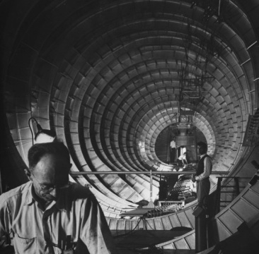
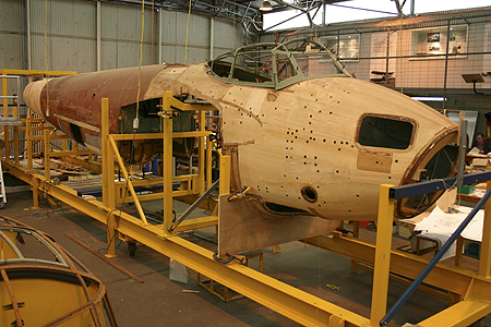
The internal cross-bracing was initially acceptable for the early single or double seater aircraft, but would obviously not provide enough room for larger passenger aircrafts. To overcome this, inspiration was taken from the long tradition and expertise in boat building which had already been applied to construct the fuselages of early wooden flying boats. The highest standards of yacht construction at the time featured “bent wooden frames and double or triple skins…with a clear varnished finish…and presented a much more open and usable fuselage interior (3)”. The well-established boat building techniques were thus passed on to aircraft construction to produce newer aircraft with very smooth, aerodynamic profiles.
Fig. 6. Semi monocoque fuselage construction of an early wooden flying boat (4)
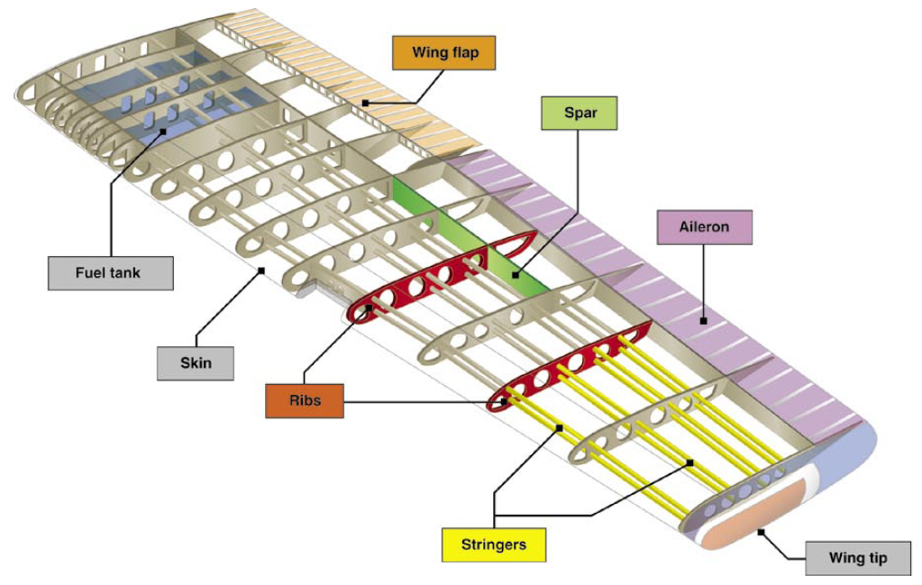
The major advantage of this type of construction is that the outer skin of the fuselage and wing no longer just define the shape and aerodynamic profile of the aircraft, but become an active load-carrying member of the structure as well. Thus, the structure becomes “multifunctional” and more efficient, unlike the braced fuselage which would be just as strong without the fabric covering the girders. As a consequence the whole structure is generally at a uniform and lower stress level, reducing stress concentrations and giving better fatigue life. Finally, as the majority of the material is located at the outer surface of the structure the second and polar moments of area, and therefore the bending and torsional rigidities are much increased. On the other hand, the thin-skinned construction means that compression and shear buckling become the most likely forms of failure. In order to increase the critical buckling loads the skins are stiffened by stringers and broken up into smaller sections by spars and ribs.
Fig. 7. Components of a semi monocoque wing (5)
Because the external skin is now a working part of the structure this type of construction became to be known as stressed skin or semi-monocoque, where monocoque means “shell in one piece” and “semi” is an english addition to describe the discrete discontinuities of internal stiffeners. The adoption of the semi-monocoque construction and a change from wood to metal naturally coincided since sheet metal production allowed a variety of thin skins to be easily manufactured quite cheaply, with better surface finish and superior material properties. Furthermore, metal construction was conducive to riveting which would overcome the adhesive problems of early wooden semi-monocoque aircraft such as the deHavilland Mosquito.
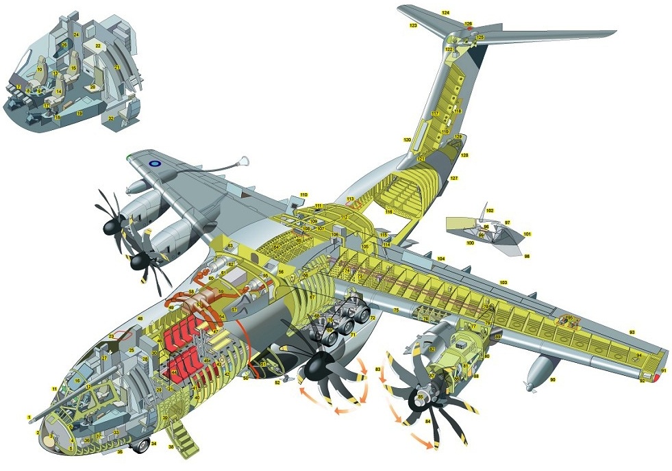
Fig. 8. Cutaway Drawing of the recently released A400M aircraft (6).
Figure 8 shows the typical construction of a modern aircraft. There have been numerous different structural arrangements over the past number of years but all generally feature some sort of vertical stiffener (ribs in the wings and rings in the fuselage) and longitudinal stiffener (called stringers). Over the years the main driver has been towards a) a reduction in the number of rivets by reverting to bonded assembly or ideally manufacturing separate components as a single piece and b) understanding the effects and growth of cracks under static and fatigue loading by building structures that can easily be inspected or have multiple redundancies (load paths). The design and manufacturing methods ofsemi-monocoque aircraft are now so automated that the development of a new aluminium, medium sized airliner “could be regarded as a routine exercise (1)”. However, the continuing legislative pressure to reduce weight and fuel consumption provides enough incentive for further development.
3) Sandwich Structures and Composite Materials
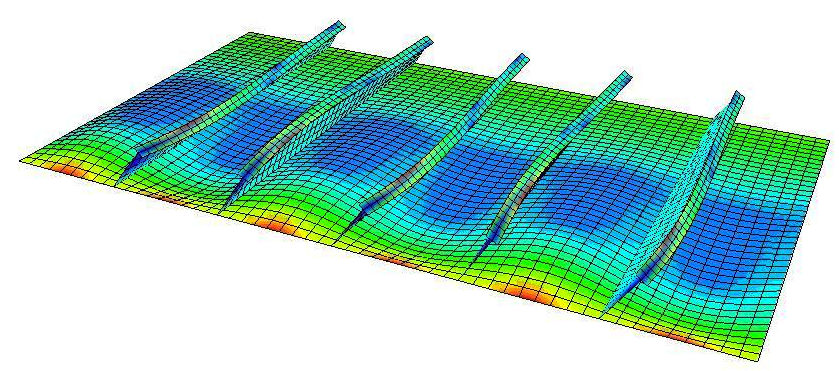
One of the major disadvantages of thin-skinned structures is their lack of rigidity under compressive loading which gives them a tendency to buckle. A sheet of paper nicely illustrates this point, since it is quite strong in tension but will provide no support under compression. One way of improving the rigidity of thin panels is by increasing the bending stiffness with the aid of external stiffeners, which at the same time break the structure up into smaller sections. The critical buckling load is a function of the square of the width of the plate over which the load is applied. Therefore skins can be made 4 times stronger in buckling by just cutting the width in half. As a wing bends upwards the main compressive loads act on the top skin along the length of the wing and therefore a large number of stringers are visible across the width.
Fig. 8. Buckling analysis of a stiffened wing panel. The stiffeners break the buckling mode shapes into smaller wavelengths that require higher energy to form compared to a single wave (7)
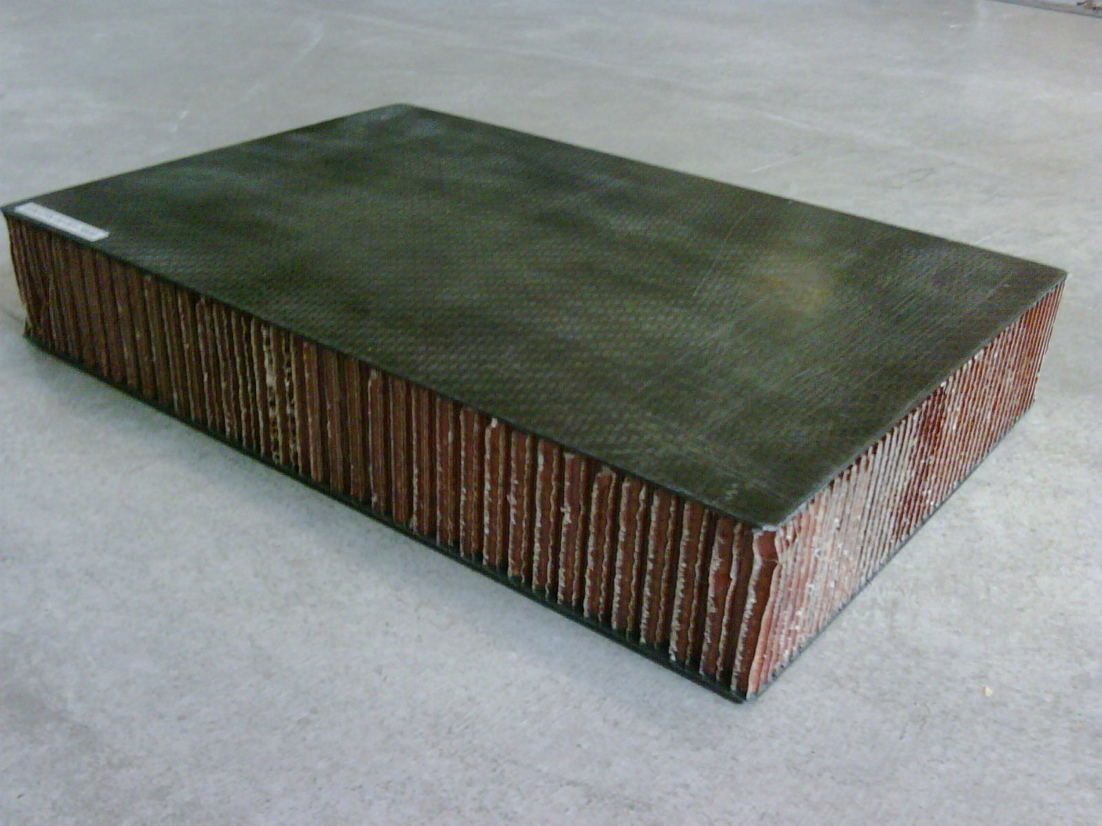
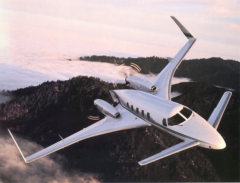
Another technique to provide more rigidity is sandwich construction. This generally features a very lightweight core, such as a honeycomb lattice or a foam, sandwiched between two thin yet stiff outer panels. Here the role of the sandwich core is to carry any shear loads and separate the two skins as far as possible. The second moment of area is a function of the cube of the depth and therefore the bending rigidity is greatly increased with this technique. Ideally, in this manner it would be possible to design an entire fuselage without any internal rings or stringers and the Beech Starship is an excellent example of a successful application. However, there are problems of forming honeycomb cores onto doubly curved shells since the material is susceptible to strong anticlastic curvature, forming a saddle shape when bent in one direction. Furthermore, there are problems with condensation and water ingress into the honeycomb cells and the ability to guarantee a good bond surface between the core and the outer skins. There is the possibility to use foam cores instead, but these tend to be heavier with lower mechanical properties. Perhaps the current trend is away from sandwich construction (10).
Fig. 9. A carbon fibre composite/honeycomb sandwich panel (9)
Fig. 10. The Beech Starship whose fuselage was design using sandwich construction with minimal internal bulkheads and ribs (8)
One of the major applications of honeycomb structures has been in combination with composite materials. Stiff carbon composite panels are the ideal candidate for the outer skins and the whole assembly can be co-cured together in an autoclave without having to perform any secondary bonding operations. Furthermore, the incredible specific strength and stiffness of carbon composites makes this combination an ultra lightweight yet resilient structure for aerospace applications. Indeed, we are now at the start of the “black” carbon age in commercial aircraft design. Apart from their excellent specific strength and stiffness properties composites exhibit the ability to tailor optimum mechanical properties by orientating the majority of plies in the direction of the load and allowing for less material waste during manufacture. As a result, the first generation of commercial aircraft that contain large proportions of composite parts, such as the Boeing 787 Dreamliner and Airbus A350 XWB, are planned to enter service throughout the next years.
Fig. 11. Considerable delamination leading to catastrophic failure (11)
Considerable effort has been made to mature composite technology in order to reduce manufacturing costs, guarantee reliably high quality laminates, understand the highly complex failure criteria and built hierarchical, multifunctional or self-healing structures. One of the major shortcomings is that the structural advantages of fibre-reinforced plastics must be viewed with respect to applications where the primary loads are aligned with the fibre direction. However, if a composite plate is subjected to significant out-of-plane stresses subsurface delaminations may develop between layers due to the weak through-thickness cohesive strength of the composite. These intralaminar delaminations are a significant problem as they are difficult to detect by visual inspection and may reduce the compressive strength of the laminate by up to 60%.
4) Novel Designs
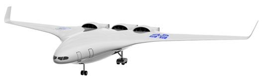
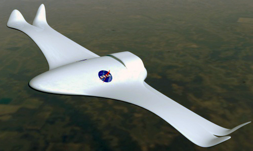
With environmental legislation becoming ever so strict it is adamant that new concepts for lightweight and fuel efficient aircraft are found swiftly. Although the pressure on developing advanced composite materials is high it must be remembered that 100 years of innovation were required to reach the stage that large metal semi-monocoque structures could be manufactured in the 1940s and another 30 years to fully understand all failure criteria. Thus we may still require significant research and development before all current issues with composite materials are resolved. Apart from carbon fibre and other composites other researchers have been looking into completely redefining the shape of aircraft. Researchers at MIT have been developing the blended wing concept and NASA are exploring the technology of morphing or shape-changing aircraft, taking inspiration directly from nature.
Fig. 12. Illustration of the MIT Silent Aircraft concept (12).
Fig. 13. NASA morphing wing aircraft (13)
Whatever the final solution might look like the next 5o years in aerospace engineering will be incredibly innovative, ground-breaking and an exciting industry to be part of!
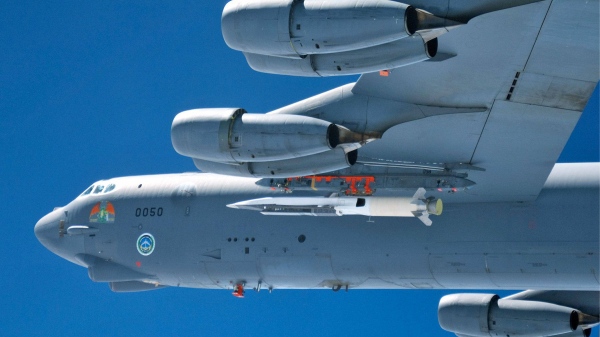
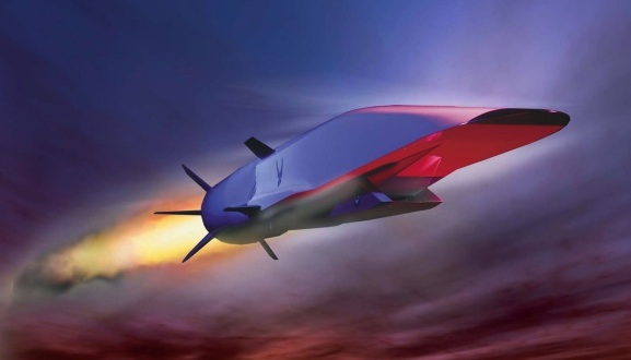
The American Air Force has reported that a test of the unmanned hypersonic X-51A “Waverider” scramjet has failed. During the test flight the aircraft disconnected successfully from the the wing of a B-52 bomber but only 16 seconds later a defect in a control fin caused the “Waverider” to spiral out of control and eventually break up over the Pacific. The test aircraft was planned to reach a top speed of 7000 km/hr and hold Mach 6 for 300 seconds. This recent event continues the series of failed tests that have plagued the project since its first flight in May 2010. Of originally four prototypes the Pentagon now has only 1 test aircraft remaining. In 2004 the older “X-43” scramjet model reached air speeds of up to Mach 10 – equal to around 11,000 km/hr.
Scramjet released from B-52 carrier wing [1]
The Scramjet Technology
A scramjet, or supersonic combustion ramjet, is a development of the ramjet engine in which combustion takes places at supersonic rather than subsonic speeds. Both engine variants require high initial vehicle velocities in order to compress and decelerate the incoming air in a converging chamber. Since the airflow throughout the engine and especially the combustion process remains at supersonic air flow the scramjet can operate more efficiently at very high flight velocities.
A model of the “X-51A Waverider” [1]
The scramjet is solely comprised of a converging inlet, a fuel injection point and a converging nozzle. As the supersonic airflow is compressed the temperature of the fluid rises to such an extent that a simple injection of gaseous fuel is sufficient to combust the chemical with the atmospheric oxygen. The combustion process raises the enthalpy of the fluid such that an expansion throughout the divergent exhaust nozzle leads to incredible acceleration of the air and consequently thrust. The principle of expanding a high-enthalpy fluid to generate thrust is similar to standard turbofan and turbojet engines, only that a scramjet does not use multiple rotating compressor stages in the inlet. As they lack mechanical compressors operation of scramjets is limited to near-hypersonic velocities since the high kinetic energy of a hypersonic flow is required to compress the incoming air to operational conditions. Thus, a scramjet-powered vehicle must be accelerated to the required velocity by some other means of propulsion.
Comparison of Turbojet, Ramjet and Scramjet [2]
The elimination of all moving parts greatly reduces the complexity, weight and susceptibility to mechanical failure of the engine. Furthermore, in turbofans and turbojets the rotating compressors are driven by turbine stages located in the diverging nozzle. The turbine stages are powered by the accelerating exhaust gases and therefore reduce the available energy output. In turbofan and turbojet engines the energy output and thrust can be directly increased by raising the turbine entry temperature i.e. burning more fuel or guaranteeing a more efficient combustion process. Throughout the years turbine entry temperatures have approached the melting point of the turbine blade metals, thus increasing the risk of static and creep failure at the highly stressed turbine inner hub. In the past, solutions to this problem included using nickel-based superalloys, thermal barrier coatings, or casting the turbine blade as a single crystal in order to remove the deformation planes at the grain boundaries. Today almost all turbine blades also feature direct air film cooling around the blades. In this technique cooler air from the compressor stages is bled to and then through channels in the turbine blades and finally allowed to flow out through tiny holes on the turbine blade surface. Ultimately this bled air is then lost from doing any useful work as combusted air. Finally, as turbofan and turbojet engines approach Mach 1 there is an issue with the flow becoming supersonic at the tips of the rotating compressor blades. Any supersonic flow will terminate in a shockwave that will disturb the uniformity of the flow throughout the compressor and cause pressure surges. This will reduce the efficiency of the compressor or even cause single blades to break off.
Thus the higher efficiency and reduced complexity makes the scramjet a better solution for hypersonic propulsion. Currently the scramjet technology would facilitate sudden airborne attacks but is not yet suited for manned flight.
Throughout the last four decades the exploitation of fibre-reinforced plastics (FRP) in engineering structures has been steadily diversifying from sports equipment and high performance racing cars, to helicopters and most recently commercial aeroplanes. Composite materials are essentially a combination of two or more dissimilar materials that are used together in order to combine best properties, or impart a new set of characteristics that neither of the constituent materials could achieve on their own. Engineering composites are typically built-up from individual plies that take the form of continuous, straight fibres (eg. carbon, glass, aramid etc.) embedded in a host polymer matrix (eg. phenolic, polyester, epoxy etc.), which are laminated layer-by-layer in order to built up the final material/structure.
All manufacturing processes are subject to a certain degree of variability. Composite materials differ from most metallic manufacturing routes in that the material is generated at the same time as the structural geometry of the part. In the aerospace industry autoclave components of pre-impregnated reinforcements are the dominant mouldings being used. In this case the hardest variable to control is the thickness dimension and this will be the major concern of this article.
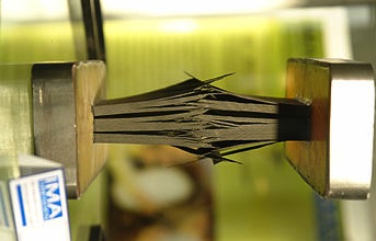
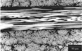
Lean manufacturing calls for variability on thickness expressed as a standard deviation of 1/6th the drawing tolerance – the “6-Sigma” tolerance band – giving a thickness defect rate of 1 in 1,000,000. In reality current thickness defect rates are in the range of 1 in 10 for composite components (1). The biggest influence on laminate thickness is the consolidation pressure. As the consolidation pressure is increased the laminate is compacted more and thus more resin may be bled out of the prepreg. As a result the volume fraction of fiber can vary from just around 50% at 1 bar consolidation to almost 70% at 6 bar. Such large variations in volume fraction will naturally influence the consolidation thickness. The external pressure “felt” by the laminate is not just a function of the target autoclave setting. Insufficient contact between the vacuum bag and the laminate and wrinkles in the bag will greatly reduce the consolidation pressure experienced by the laminate. Since the vacuum bag application is a manual process and the bagging material can be quite flimsy certain amount of wrinkling is inevitable. Thus it can be very difficult to reduce this type of variability and in the worst-case defects such as delaminated plies may occur.
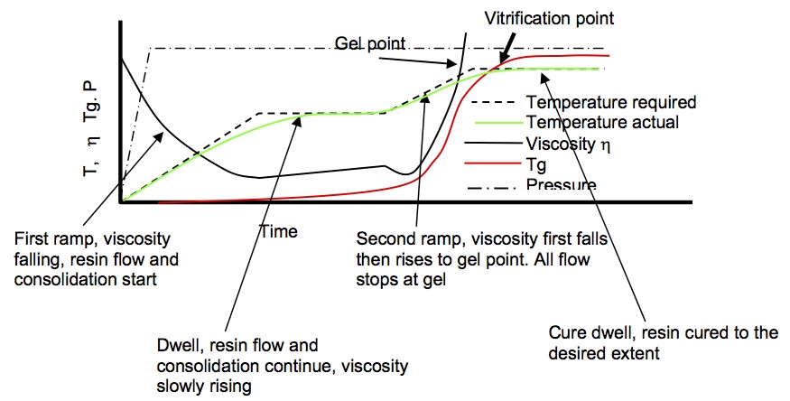
During curing the external temperature is typically ramped up in two stages and held constant in between, the so-called “dwell period”, in order to allow the actual mould temperature to catch-up and ensure full consolidation and cure. During the early parts of the cure the resin viscosity will first reduce as a result of the increasing temperature but then increase suddenly as the mould temperature reaches the gelation point and thus causes the resin to solidify. When the resin viscosity is low internal flows of resin will occur.
Composite Consolidation Programme: Variation of Viscosity with Temperature (3)
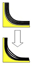
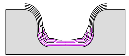
Around corners the difficulty of preventing fibre wrinkling or fibre bridging is added. If plies cannot slip over each other as they consolidate over inside radii, fibre bridging will occur and the laminate will get thicker in the corner. The fibres that bridge the radius will directly react the consolidation pressure leading to a reduced resin pressure beneath the bridged fibres. Resin will, therefore, tend to flow towards this region of bridged fibres but if this does not sufficiently occur high local voidage will result.
Fibre Bridging (3)
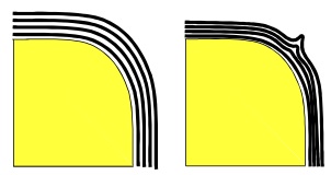
Fibre Wrinkling (3)
Upon consolidation the resin will start to shrink and since it is constrained, the bridged pocket will be exerted under tensile stress. This may cause cracking in the brittle resin and thus cause internal failure before any external load has been applied on the part. Fibre bridging may be reduced by using rollers to press the fabric into the corner or by incorporating slip-lines into the layup. However, especially in the latter case this will complicate the layup and increase manufacturing times.
Slip Lines in Layup (3)
Equally, if plies cannot slip over external radii then fibre wrinkling or “earing” will occur. Although this will not produce a resin sink the wrinkled area will be voidy and have poorly controlled fibre orientation leading to a reduction in mechanical properties. Fibre wrinkling may also be exacerbated by wrinkles in the vacuum bag over the corner.
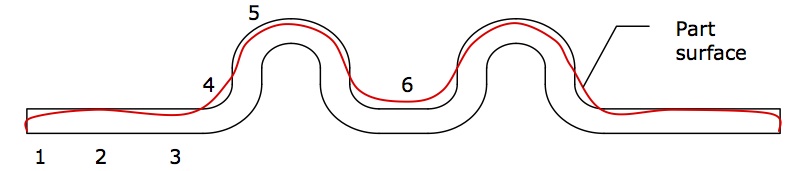
Taking the example of the component below the real laminate thickness and target thickness can be widely different. In zone 1 the laminate is likely to be thinner as a result of resin bleeding out of the component unless some sort of resin dam is used. Zones 3 and 5 are likely to be thinner due to resin flow from these areas into the resin sink over the internal radii at zone 4. Ideally the effects of internal and external radii would cancel out at zones 4 and 5 but inaccuracies in the layup or induced tensions in the plies will typically mitigate this. The most critical section of the component is undoubtedly zone 6, where high voidage is very likely due to the difficulty of bleeding sufficient resin into the area and the two adjacent internal radii.
Thickness Variation in Composite Moulding (3)
Thickness deviations are only one form of variability. Other defects may stem from part design, manufacturing design, the lay-up process or the autoclave process. To produce reliable components with tightly toleranced dimensions lay-ups are typically made balanced (equal number of ±Angle° plies) and symmetric about the mid-plane in order to avoid thermally induced distortions. Unbalanced or unsymmetric laminates manufactured as plates on flat tools will warp and twist as a result of the different thermal expansion coefficients of different layers. However, if the resin content varies between different plies the thermal properties will naturally vary and the laminate will be unbalanced. For a typical pre-preg the weight/unit area tolerance limits can be up to 5% on both pre-preg and fibre weight, and resin contents may even have a slightly wider tolerance band (1). Considering that resin and fibre contents directly influence the mechanical properties of the composite it can be quite challenging to decrease variability and guarantee reliable components with such a wide tolerance band.
Additional distortions arise if aluminium or steel tooling is used. Metal tools have higher coefficients of thermal expansion than composites and cure in the autoclave can occur at elevated temperatures of typically 180°C. Therefore the tooling will expand more than the composite, putting strains onto the outermost ply. These surface strains may be exacerbated by local features such as a corners and joggles.
A considerable amount of variability around corners is the so-called “spring-in” effect. As the laminate cools down from cure it will contract far more through the thickness than in plane. In order to maintain continuity of the profile without causing residual stresses the corner angles will close up. This can result in changes of corner angle of about 1° for 150°C change in temperature. Other defects such as fibre wrinkling or bridging will worsen this effect. In general it is very difficult to accurately predict what will happen for certain geometries.
Composite Spring-In (3)
In addition, other sources of defects include:
Surface scratches, depressions and dents
Delaminations between plies or voids
Material inclusion within the layup such as a ruler
Undercure or overcure (burning)
Tool drop or other impact events that can cause internal resin damage or delaminations
In general most of these defects can be controlled by well-trained and highly motivated factory staff. Engineers and factory management should work together to ensure that all employees involved with the layup and curing process are aware of all possible sources of variability and how to mitigate these. In this respect detailed technical training entrusts more responsibility on the shoulders of employees and gives the staff the deserved recognition of being an important cog in the works of the company. Furthermore, the importance of a well-lit, comfortable working environment and positive atmosphere should not be understated and can go a long way to guaranteeing high-quality mouldings. A well-trained, highly motivated and happy staff is the first line of defence against poor parts.
Next it is important to follow a concurrent design philosophy throughout the development process of a component. Thus the design, stress, manufacturing and quality control engineers must simultaneously work together in order to come up with a solution that fulfils all functional needs but can also be manufactured to a profit without unnecessary defects. The classical philosophy of separately designing a functional component, which is handed to the production engineers, makes manufacturing high-quality laminates incredibly difficult and will incur significant secondary costs.
Finally, specific details of possible sources of variability can then be handled on a case-by-case basis. Thus the component’s shape and type of prepreg to be used will influence the mould material shape design; curing temperature and pressure; possible inclusion of slip lines and laminate stacking sequence as discussed above. In conclusion, manufacturing high-quality laminates for the aerospace industry is not an easy task and is even more daunting considering the size of the current all composite Boeing 787 Dreamliner and Airbus A350 XWB projects. Each design decision must be weighed against the influence on manufacturing process and every little detail is important!
References
(1) Potter, Kevin (1996). An Introduction to Composite Products: Design, Development and Manufacture. Springer, 5th Ed. Chapman & Hall, London.
Throughout the last four decades the exploitation of fibre-reinforced plastics (FRP) in engineering structures has been steadily diversifying from sports equipment and high performance racing cars, to helicopters and most recently commercial aeroplanes. Composite materials are essentially a combination of two or more dissimilar materials that are used together in order to combine best properties, or impart a new set of characteristics that neither of the constituent materials could achieve on their own. Engineering composites are typically built-up from individual plies that take the form of continuous, straight fibres (eg. carbon, glass, aramid etc.) embedded in a host polymer matrix (eg. phenolic, polyester, epoxy etc.), which are laminated layer-by-layer in order to built up the final material/structure.
In terms of manufacturing advanced fibre-reinforced composites the single most important aspect to recognize is that the material and the structure are created at the same time. Consequently any defects that are induced during the manufacturing process directly influence the strength and stiffness of the material and structure. Every little detail is important.
A large number of composite manufacturing processes have been developed over the last 40 years including: contact moulding, compression moulding, vacuum bag/autoclave moulding, rotational moulding, resin transfer moulding (RTM), tape wrapping, filament winding, pultrusion, expanding bladder moulding etc. All these processes have several characteristics in common; the reinforcements are brought into the required shape in a tool or mould, resin and fibres are brought together possibly under elevated temperature and pressure to cure the resin, and the moulding stripped from the part once the resin has cured. The different fabrication techniques can either be classified as direct processes (eg. RTM, pultrusion, contact moulding) that use separate fibres and resin brought together at the point of moulding or indirect processes that use fibres pre-impregnated with resin (eg. vacumm bag/autoclave moulding, compression moulding).
The selection of the manufacturing process will naturally have a great effect on the quality, the mechanical properties and fabrication cost of the component. According to Potter (1996) an ideal process can be defined as having:
High Productivity – short cycle times, low labour contents etc.
Minimum materials cost – low value added materials, low material storage and handling cost
Maximum geometrical flexibility – shape complexity and size of component
Maximum property flexibility – range of matrices, range of reinforcement types, ability to control mechanical properties and tailor characteristics
Minimum finishing requirements – net shape manufacturing
Reliable and high quality manufacture – low reject rates, low variability etc.
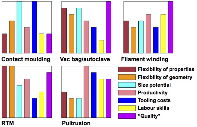
Comparison of Composite Manufacturing Techniques (1)
No manufacturing process exists that can simultaneously fulfill all these requirements; most importantly some of these requirements may be mutually exclusive. A comparison of the 5 most common processes is shown below.
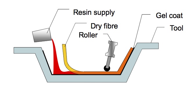
Contact Moulding
This is the oldest and most primitive manufacturing process but also the most widely used around the world. In contact moulding resin is manually applied to a dry reinforcement placed onto a tool surface and can be compared to glueing wall paper with a brush. The tool and fabric are then enclosed by a vacuum bag and the air under the bag removed in order to cure the laminate under atmospheric pressure. However, since the applied pressure is relatively low and cure typically occurs at room temperature the volume fraction of reinforcement is limited to the natural packing density. Furthermore, the quality is totally dependent on the skill of the workforce and due to the difficulty in reliably guaranteeing high-quality laminates it is almost impossible to qualify contact moulded structural components for commercial aircraft. Finally, due to the limited external pressure voidage is difficult to control, which has a great effect on the variability in the thickness of laminates.
Contact Moulding Schematic (1)
On the other hand the process is highly flexible, ideal for one-off-production and requires minimal infrastructure. While contact moulding is process of choice for very large structures the geometrical flexibility is more constrained in terms of creating parts with fine details, corner radii, etc. For this reason the process is extensively used in glassfibre/polyester resin shipbuilding and for gliders.
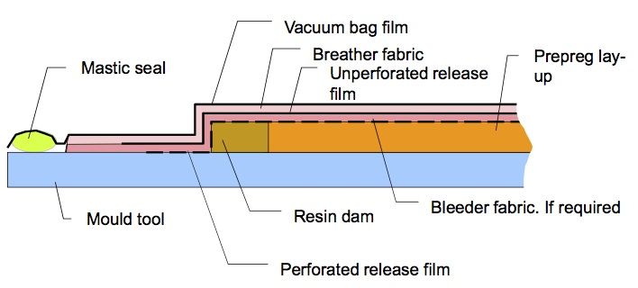
Vac. Bag/Autoclave
In advanced composites autoclave processes are by far the most widely used and autoclave moulding is the process of choice for the aerospace industry. These processes use pre-impregnated uni-directional plies or woven cloths, which have been partially cured or beta-staged. One disadvantage is that pre-preg has to be kept in a freezer in order to prevent the resin from going-off. Multiple prepreg plies are laid down onto a tool surface with the pre-defined fibre orientations, to build up the required thickness, and then covered with a release film, breather fabric and a vacuum bag or silicon pressure bag. The air is drawn out from the bag to create a vacuum and the tool heated under elevated temperature and pressure to cure the resin. In principle multiple demoulding cycles are performed by covering the laminate and applying a vacuum after every 3-4 ply layers in order to remove any excess air between layers. This reduces the bulk factor and helps to prevent delaminations between plies and controls the thickness dimension. Regular demoulding cycles and sufficient hydrostatic pressure on the part during curing are the two basic requirements for achieving good mouldings. The productivity of autoclave moulding is generally quite low since the manual lay-up, bagging and demoulding cycles consume significant labour and time. Furtermore, the capital expenditure of autoclaves are enourmous, which constrains its use to larger structures where these expendictures are justified. Since, pre-preg is no longer in a low-value added state the material costs are also higher.
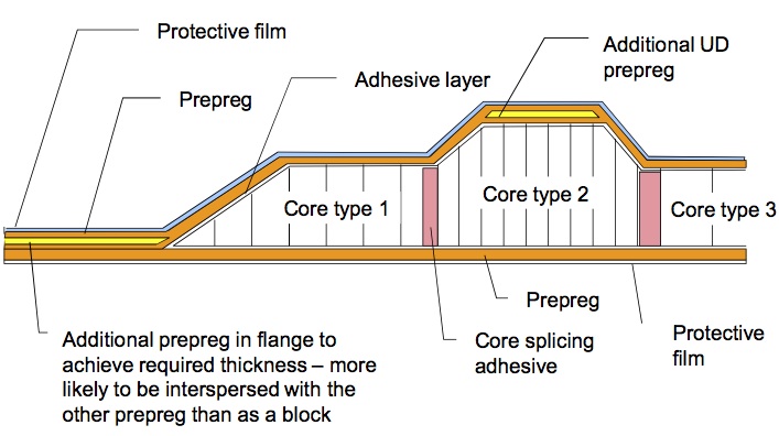
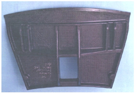
Prepreg Layup for Autoclave Cure (1)Honeycomb Sandwich with Pre-preg for Autoclave Cure (1)
Geometrical flexibility in both shape and size are better than for most processes. Recently it has been possible to manufacture the entire floor of a helicopter in one piece, which would not be possible with a metallic approach. Autoclave mouldings are often used in conjunction with honeycomb cores such that very lightweight components can be manufactured. This is one of the reasons why the dominance of autoclave mouldings seems very likely to continue in the near future, at least in the aerospace environment.
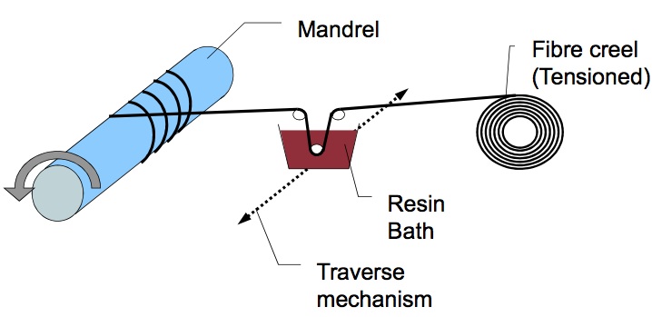
Filament Winding
In filament winding a tow of fibres is passed through a bath of resin and wound onto a revolving mandrel by traversing longitudinally along the axis of the rotating mandrel. Unless tacky pre-impregnated fibre tows are used the path followed by the tow must closely follow a geodesic path (fibre paths that do not cause fibres to slip if tensioned). Any simple helical path on a cylinder is defined to be a geodesic path but once curvature in two directions is introduced (e.g. a globe) the number of possible paths becomes very limited. For this reason property flexibility is rather constrained such that filament winding is typically used for manufacturing pipework, pressure vessels and rockets motors. Especially, pressure vessels are conducive to filament winding since they have two clearly defined stress-directions (the hoop and longitudinal stresses) that can be accommodated by the winding direction.
Schematic of Filament Winding Process (1)
One disadvantage of filament winding is that the mandrel is often enclosed within the winding. If a liner of metal or polymer is used as a mandrel it may form a permanent part of the structure but it is more common that the winding is slit-off at the ends to demould the part. The geometrical flexibility is also constrained by having to wind around circular or prismatic mouldings. One major advantage is that the process lends itself to automation such that cycle times and labour costs can be kept low with high reliability and quality. This latter aspect is one of the reasons why efforts are being made to widen the process’ geometrical limits and possible applications.
Resin Transfer Moulding (RTM)
RTM can not be considered as a single process but is better regarded as a “manufacturing philosophy in which the resin and fibres are held apart until the very last moment” (Potter, 1996). However, all process variations have the common features of holding unresinated fibres within a closed tool cavity with a differential pressure applied to a supply of resin such that the resin permeates into the reinforcement. The tool may be rigid or contain flexible elements. The consolidation pressure on the tool is applied by means of mechanical clamps, a tooling press or the use of internal vacuum and defines the achieved volume fraction of fibre with respect to resin. RTM has been used since the 1970s to build radomes as well as aeroengine compressor blades. The main driver behind further developing RTM processes is to devise fabrication methods that can overcome the geometrical complexity limitations imposed by autoclave mouldings. In terms of productivity cycles times are lower than most other processes and in the automotive industry small components are manufactured within minutes.
Automotive Panel Manufactured via RTM
A major advantage of RTM is the use of low added value materials (dry fibres and low viscosity resins) which do not have to be stored in freezers, thus driving down material and handling costs. The major advantages of RTM however lie within their geometrical and property flexibility. RTM can be used with UD stitched cloths, woven fabrics and 3D fabrics, and the resin injection can be varied to control the volume fraction and therefore the stiffness and strength of the component. Furthermore, small components with very fine details are manufactured on rigid metal tooling while larger components can be produced on flexible moulds. Finally, with a closely controlled process it is possible to create net-shape mouldings with minimal finishing requirements. However, all this comes at the cost at a slightly trickier production technique. In order to guarantee high-quality components the resin injection and resin flow has to be closely controlled such that all of the reinforcement is equally wetted-out. This requires quite advanced fluid dynamics simulations and extensive testing in order to come up with a mould shape that allows even resin flow to all parts of the component.
Pultrusion
In this process fibres are drawn from a creel board and passed through a resin bath to impregnate the fibres with resin. The impregnated fibres are then passed through a pre-die to remove any excess resin and to pre-form the approximate final shape. The curing die is then entered, which takes the shape of the final required cross-section of the pultruded part. The curing die applies heat to the component to consolidate the resin and the cured, shaped profile is pulled from the die under tension. This means that productivity can be very high in an ongoing production but will fall for lower production volumes that require changes to new cross-section dies. Since the operation is automated labour costs are low and the reliability and quality of components is high. The process is generally limited to constant cross-section components, which greatly restricts applications. Pultrusion has been used very little in aerospace environments but has found application in manufacturing standardized profile beams for civil engineering structures.
Schematic of Pultrusion Process (1)
Automated Processes
The use of robotics in composite manufacturing is growing at a rapid rate and is probably the most promising technology for the future. Obvious advantages of automating the manufacturing process include reduced variability in dimensions and less manufacturing defects. Furthermore, the feed material can be used more efficiently and labour costs are reduced. One promising class of system are the so-called Automated Fibre Placement (AFP) machines which use a robotic fibre placement head that deposits multiple pre-impregnated tows of “slit-tape” allowing cutting, clamping and restarting of every single tow. While the robotic head follows a specific fibre path tows are heated shortly before deposition and then compacted onto the substrate using a special roller. Due to the high fidelity of current robot technology AFP machines can provide high productivity and handle complex geometries. Current applications include the manufacture of the Boeing 787 fuselage and winding of square boxes, that are then slit lengthwise to make two ‘C’ sections for wing spars. Integrated manufacturing systems as designed by companies like ElectroImpact offer exciting turnkey capabilities for future aircraft structures. These systems combine multiple manufacturing processes, for example fibre placement and additive manufacturing on one robot head, and therefore facilitate the production of blended and integrated structures with fewer joints and connections. These systems will also allow engineers to design more efficient structures, such as integrated orthogrid or isogrid composite panels, that are currently hard to manufacture economically on a large scale.
References
(1) Potter, Kevin (1996). An Introduction to Composite Products: Design, Development and Manufacture. Springer, 5th Ed. Chapman & Hall, London.
Throughout the last four decades the exploitation of fibre-reinforced plastics (FRP) in engineering structures has been steadily diversifying from sports equipment and high performance racing cars, to helicopters and most recently commercial aeroplanes. Composite materials are essentially a combination of two or more dissimilar materials that are used together in order to combine best properties, or impart a new set of characteristics that neither of the constituent materials could achieve on their own. Engineering composites are typically built-up from individual plies that take the form of continuous, straight fibres (eg. carbon, glass, aramid etc.) embedded in a host polymer matrix (eg. phenolic, polyester, epoxy etc.), which are laminated layer-by-layer in order to built up the final material/structure.
An example of a composite laminate (1)
Cross-Section of composite laminate. The individual fibres and surrounding matrix are clearly discernible (2)
In the aerospace industry the benefits of exploiting the excellent specific strength and stiffness properties (strength and stiffness per unit weight) of composites in terms of lightweight structural design are immediately apparent. Furthermore, the laminated nature of high performance composite materials enables the designer to tailor optimum mechanical properties by orientating the fibre direction with the primary load paths. As a result, the first generation of commercial aircraft that contain large proportions of composite parts, such as the Boeing 787 Dreamliner and Airbus A350 XWB, are planned to enter service in the near future. Other advantages of fibre reinforced plastics, such as the relative ease to manufacture complex shapes, and their excellent fatigue and corrosion resistance, have made FRP composites increasingly attractive in the renewable energy sector.
Composite materials have actually been around for quite a long time. As early as 3000 B.C. the ancient Egyptians embedded straw in their mud bricks in order to control shrinkage cracks and improve the tensile strength. Furthermore, papyrus based cartonage and paper maché were used to make mummy cases. In fact, manufacturing tubular shells using metals is quite difficult such that this ancient approach remains an important exploitation of composites today. Of course none of these materials would be suitable for the high performance requirements of the aerospace industry.
Mud and Straw Brick (3)
It was not until the invention of phenolic resin in 1909 that composites took-off in aircraft. The most famous example was the deHavilland Albatross transport aircraft manufactured from a ply-balsa-ply sandwich fuselage construction, which was later developed into the deHavilland Mosquito multi-role combat aircraft for WWII. The large-scale wooden construction made the Mosquito extremely light, fast and agile. Furthermore, the Mosquito was cheaper than its metallic counterparts and allowed highly skilled carpenters from all over the UK to be contracted to help with the war effort. One disadvantage of early phenolic resins was their inability to cope with hot-wet conditions such that the Mosquito became notorious for disintegrating in mid-air in the Pacific War arena.
DeHavilland Mosquito Timber Fuselage (4)
Since the development of carbon and glass fibres in the 1950’s the aerospace industry is steadily moving towards “all-composite” civil aircraft. The most common fibre and resin types used today are:
Fibres
Glass
Carbon
Aramid – Kevlar™
Diameter ≈ 10 mm
Diameter ≈ 8 mm
Stiffness ≈ 125GPa in tension
Strength > 3GPa due to lack of defects on small diameter fibre
Strength > 5GPa due to highly aligned planes of graphite
Strength > 3GPa because of highly aligned linear polymer chains
Stiffness ≈ 70 GPa for cheaper E-glass and 85 GPa for more expensive R- or S – Glass
Stiffness ≈ 160-700 GPa but 230-400 GPa is the usual
Much weaker and less stiff in compression as linear polymer chains come apart
Susceptible to environmental attack and fatigue
Not susceptible to degradation by chemicals and good in fatigue
Susceptible to degradation by UV light and moisture
Fibres need silane treatment to bond well to matrix
Fibres bond well with surface treatment
Fibres do not bond well at all leading to a weak fibre/matrix interface
Used in boats, wind turbine blades and other cost critical applications
Expensive material cost limits use to high performance applications were the higher mechanical properties are justified i.e. Racecars, aerospace etc.
Weak interface gives excellent energy absorption. Thus used for bullet-proof vests, helmets and impact protection on aircraft
Matrix
Phenolic
Polyester
Epoxy
First modern resin
Most commonly used matrix
Most common in aerospace
Tends to be brittle
Resin can be quite tough
Can be made quite tough
Wets out fibres badly
Wets out reinforcement very well
Wets out reinforcements very well
Good chemical, heat and fire resistance and don’t produce toxic gases in a fire
Poor chemical resistance and burns very easily
Good chemical resistance but will burn
Thus used in aircraft interiors
Very cheap resin used alongside glass fibres in boat hulls, wind turbine blades and other cost critical applications
Generally used in combination with carbon fibre for high performance, lightweight applications
The shift from metallic to composite construction has naturally induced a change in the design methodology of aircraft components. It has to be borne in mind that not only the mechanical properties of composites differ from those of metals, but that a whole range of physical and chemical properties are different.
– All composites have relatively low through-thickness thermal conductivities and thermal expansion coefficients in and out of plane may be widely different. Therefore thermal expansion mismatch stresses at attachment points can be a problem.
– Composites can be made with very high translucency to electromagnetic radiation eg. X-Ray.
– Electrical conductivity of composites is generally fairly low. Consequently, a copper mesh is often integrated in aerospace laminates to protect against lightning strike damage. However, this compromises a lot of the potential weight savings.
– Direct contact between carbon fibre reinforced plastics and aluminium components will corrode the aluminium over time. Therefore contact between carbon and aluminium at lug attachments and joints has to be prevented.
– All resins pick up water and their properties change as a result of this.
– Composites are not very resistant to mechanical wear effects. External surfaces may need treatment prior to painting.
– Composites tend to have relatively low stiffnesses on an absolute basis, from <10% to about 60% of steel.
– The failure modes in composites are very diverse and include fibre failure, resin failure, fibre/matrix debonding, delaminations etc., which generally increases the analytical workload. Often these failure modes are related such that it can be difficult to exactly predict the failure load.
– Composites will absorb impact energy by damage modes rather than local plastic deformation. This means failure is typically sudden and catastrophic without any prior warning that the structure has been overloaded.
– Fatigue, stress rupture and creep resistance varies from rather poor for glass FRP in wet conditions to excellent for many carbon FRP layups.
Especially due the uncertainty of correctly modelling the complicated failure modes, engineers have tended to revert to a “black” aluminium approach that has inhibited the full exploitation of composite materials in terms of potential weight savings. However, the ongoing research activities into advanced composites and increasing teaching in higher education will hope to resolve these issues in the near future.

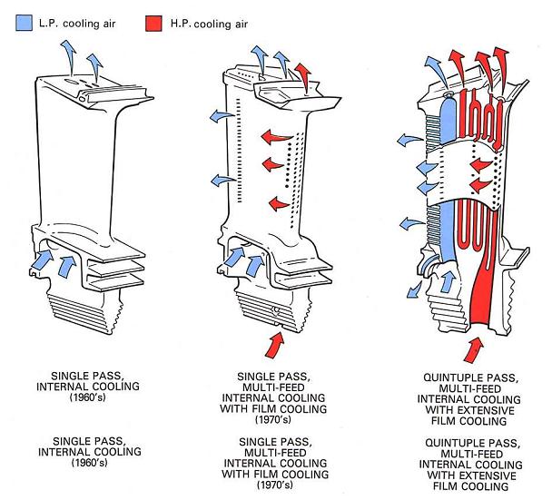
![Fig. 1. Triple Stage Turbine [2]](https://rgroh.com/wp-content/uploads/2013/04/triple-stage-turbine.jpg)
![Fig. 2. Velocity triangles for turbine stage [2]](https://rgroh.com/wp-content/uploads/2013/04/fig9VelTrianglesTurbine_web.jpg)
![Fig. 3. The microstructure of the three different turbine blades [4].](https://rgroh.com/wp-content/uploads/2013/04/img014.jpg)