Author: Rainer Groh

  • Optimising the support structure and rotor count of multi-rotor wind turbines

    Optimising the support structure and rotor count of multi-rotor wind turbines

    Wind energy is expected to be one of the central pillars of a low-carbon electricity system, and for the past few decades the industry has pursued a single, simple strategy to push costs down: build bigger. Each new turbine generation carries a larger rotor than the last, because — up to a point — a longer blade sweeps more area and captures more energy. But the trend cannot continue indefinitely. As blades grow, the mass of blades, generator and nacelle climb faster than the power they produce, and the practical headaches of manufacturing and transporting large components begin to factor. Eventually the cost of going bigger outweighs the extra energy, and the levelised cost of energy (LCoE) — the price of electricity averaged over the lifetime of the turbine — stops falling.

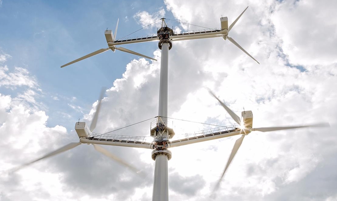
    One way around this ceiling is to stop thinking of a turbine as a single rotor. A multi-rotor wind turbine (MRWT) replaces one very large rotor with a coplanar array of many smaller rotors mounted on a shared support structure. The installation occupies a similar footprint and produces the same total power, but the individual blades are short enough to be considerably easier and cheaper to build and transport. Smaller rotors also mean less material overall and the system can keep producing energy even if a rotor fails.

    This is the promise, at least. The difficulty is that nobody can yet say with confidence how large these savings really are. The theoretical argument most often cited in support of multi-rotors — a “square-cube law” of scaling — is not borne out by simulation data, and there are few physical installations or detailed design studies to check against. Most existing studies take shortcuts: they reuse rotors designed for conventional single-rotor machines, simplify or ignore important ways the structure can fail, or tend to conclude that increasing rotor count indefinitely always lowers costs — a result that is unlikely to hold in practice.

    In a recent paper presented at the Torque 2026 conference, we set out to close that gap with a more honest design process. The work uses an in-house aeroelastic optimisation tool, ATOM, to design a multi-rotor turbine from first principles. “Aeroelastic” simply means the calculation accounts for both the aerodynamic loads imposed by the wind and the way the structure deforms in response; “optimisation” means the software automatically searches for the design that minimises cost. Importantly, the rotors are not borrowed from single-rotor turbines — they are drawn from an open library of rotors (blog post here) we optimised specifically for the multi-rotor context in earlier work.

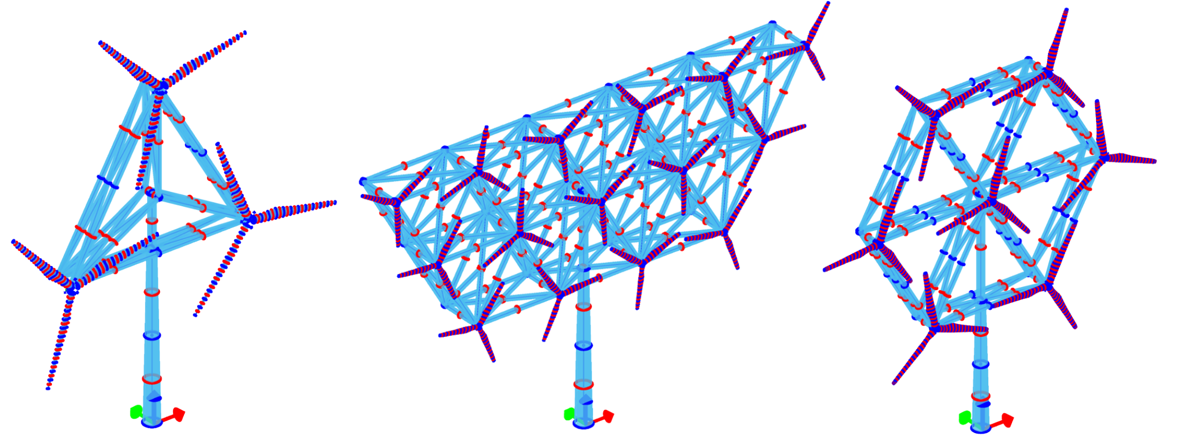
    Designing a multi-rotor turbine means answering two intertwined questions at once: how many rotors to use, and how to arrange and size the support structure that holds them. We tackle this with a “tiered” approach. For each candidate number of rotors, the software lays out the arrangements that are geometrically feasible — square grids, hexagons, pyramid-like stacks — and then designs the lightest support structure that can sustain loads in each case, checking every member against strength, buckling and fatigue failure. The competing arrangements are ranked by cost of energy to choose the best one for that rotor count. As a demonstration, optimising the support structure of a seven-rotor, 3 MW turbine reduced structural mass by nearly 70%.

    The ultimate aim of this work is not to hand industry a ready-to-build blueprint, but to make a fair comparison possible. Because we now optimise both the rotors and the structure that carries them — rather than scaling up off-the-shelf parts — the eventual head-to-head comparison against an equivalent single-rotor turbine should be more representative than previous attempts. This conference paper is a deliberately preliminary step: it demonstrates the framework on individual cases, and the next stage is to sweep across a wide range of rotor numbers to locate the genuine sweet spot for a given power rating. Only then can we offer a credible answer to the question if multi-rotor turbines actually make wind energy cheaper.

  • Open-source reference rotor library for multi-rotor development and innovation

    Open-source reference rotor library for multi-rotor development and innovation

    Wind energy is expected to play a central role in the global transition to low-carbon electricity. Over the past decades, the dominant design for wind turbines has been the single large rotor mounted on a tall tower. However, as turbines continue to grow in size, engineers face increasing challenges related to transportation, manufacturing, structural loads, and cost.

    One alternative concept that has attracted growing interest is the multi-rotor wind turbine (MRWT). Instead of one very large rotor, a multi-rotor turbine uses many smaller rotors mounted on the same structure to achieve the same overall power output. This approach could offer several potential advantages: smaller blades are easier to manufacture and transport, maintenance can be simplified, and the system may continue operating even if one rotor fails. In some cases, interactions between the rotors may even slightly increase the total power generated.

    Despite this promise, research on multi-rotor systems has been limited by a practical issue: the lack of suitable reference rotor designs that researchers can use for modelling and comparison. Most existing wind-turbine reference models were created for single-rotor systems and are not well suited to studying arrays of smaller rotors.

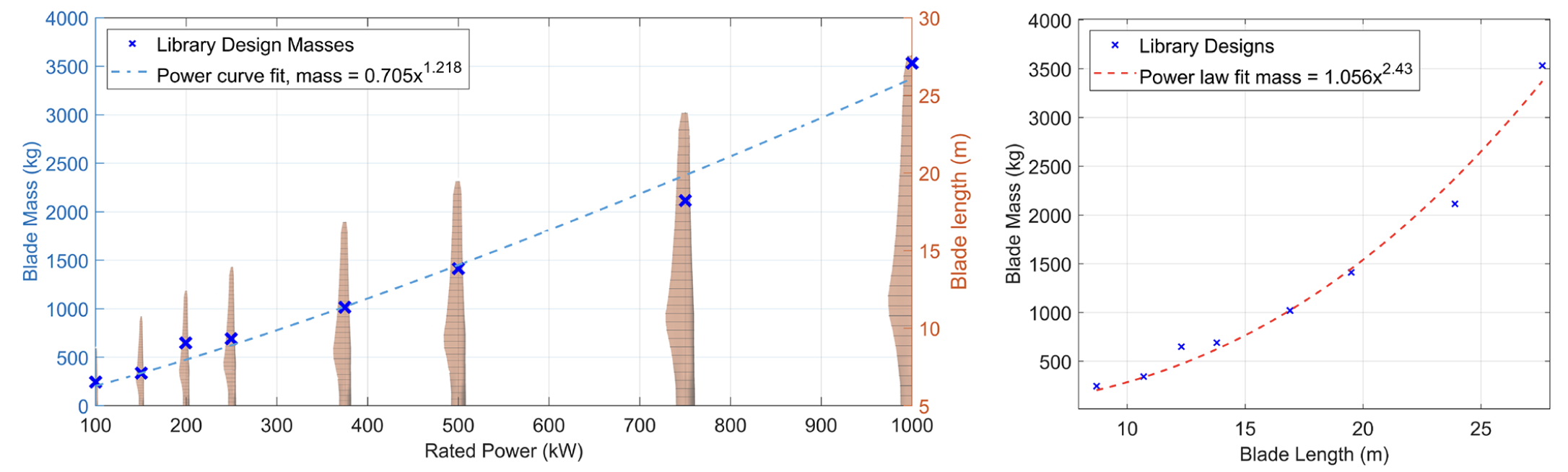
    To address this gap, we have developed an open-source library of optimised wind-turbine rotors, covering rated powers from 100 kW to 1 MW. These rotor designs were created using aeroelastic optimisation methods, which consider both aerodynamic performance and structural behaviour. The optimisation process enabled the design of blades that balance energy production, structural safety, and material use.

    A key feature of the library is that the designs are fully open and compatible with widely used simulation tools. This means researchers around the world can use the models directly in their own studies. The library also includes a method for interpolating between designs, allowing new rotor sizes to be generated between the predefined ratings.

    By providing a shared set of reference designs, this work aims to make it easier to explore questions such as:

    • How many rotors should a multi-rotor turbine have?
    • How do rotor interactions affect performance and loads?
    • Can multi-rotor systems reduce the cost of wind energy?

    Ultimately, the goal is not to produce “ready-to-build” turbine blades, but rather to provide a flexible starting point for research and innovation.

  • Hummingbird beak inspired soft robotics

    Hummingbird beak inspired soft robotics

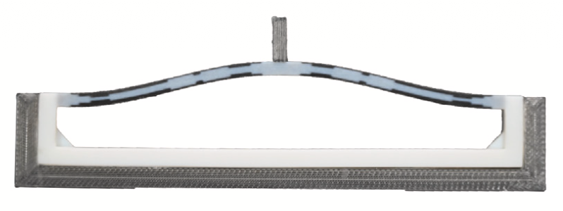
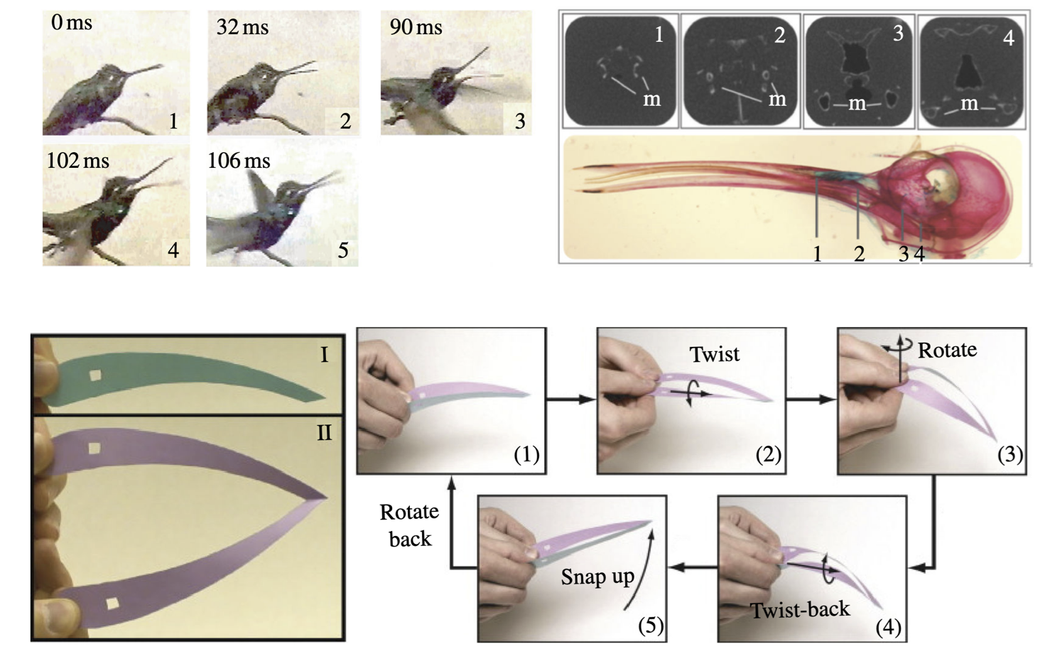
    Nature often solves engineering problems in ways that are both elegant and efficient. A striking example can be found in the beak of the hummingbird. When a hummingbird captures an insect, its beak snaps shut with remarkable speed. What is fascinating about this motion is that it does not rely purely on muscular force. Instead, the geometry of the beak itself helps store and rapidly release elastic energy.

    Our work explores how this natural mechanism can inspire new morphing structures in engineering. In particular, we investigate snap-through, a mechanical instability in which a structure suddenly transitions from one stable shape to another. Many people have experienced this behaviour when pressing on a rubber cap that suddenly everts. The motion appears instantaneous because the structure slowly stores elastic energy and then releases it all at once.

    The central question of a recently published paper was: how much does the shape of the hummingbird inspired structure matter?

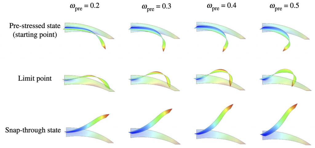
    Using computational models, we systematically varied the geometry—such as curvature and cross-sectional shape—and observed how these changes affected the speed and intensity of the snap-through motion.

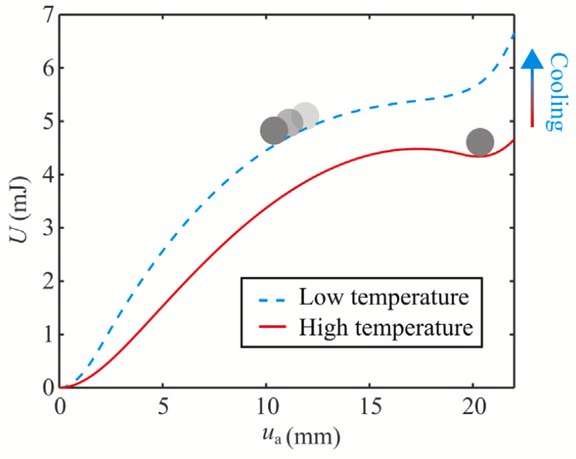
    Snap throug behaviour of the hummingbird beak inspired structure with different levels of pre-rotation

    What emerges is a clear message: geometry is not just a detail—it is the mechanism. Small geometric changes can dramatically alter how much elastic energy is stored before instability occurs, and therefore how fast the structure moves when it snaps. Some geometries allow the structure to accumulate energy efficiently and release it in an extremely rapid motion.

    Interestingly, the geometries that produce the most effective snap-through behaviour resemble the shapes we observe in real hummingbird beaks. This suggests that biological systems may naturally exploit these mechanical principles.

    Why does this matter for engineering? Because snap-through offers a way to generate fast motion without large motors or complex mechanisms. By carefully designing geometry, we can create structures that move quickly, reliably, and efficiently. Such ideas could inform the design of soft robotic grippers, deployable aerospace structures, or rapid mechanical switches.

    More broadly, the study illustrates a recurring theme in structural mechanics: performance often emerges not from stronger materials, but from the intelligent use of geometry and instability. When we learn how to harness these effects—many of which nature already uses—we can design structures that are both simpler and more capable.

  • Using origami to explain clicking sounds produced by moths

    Using origami to explain clicking sounds produced by moths

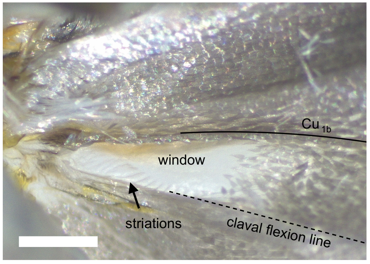
    Moths are not usually thought of as noisy animals, but some species produce rapid bursts of ultrasonic clicks that interact with the echolocation systems of hunting bats. In ermine moths (Yponomeuta), these sounds originate from a small structure on the hindwing known as a tymbal. The mechanics behind how this tiny feature generates sound are surprisingly rich and provide an interesting example of how biological structures exploit mechanical instabilities.

    The tymbal consists of a narrow band of ridges located along a natural fold in the wing. As the moth flaps, this region deforms under aerodynamic and inertial loads. Our work shows that the ridges do not simply bend smoothly. Instead, they undergo sequential snap-through buckling: each ridge flips between two stable shapes one after another. Every snap produces a short mechanical impulse, and the series of snaps during a wingbeat results in a burst of ultrasonic clicks.

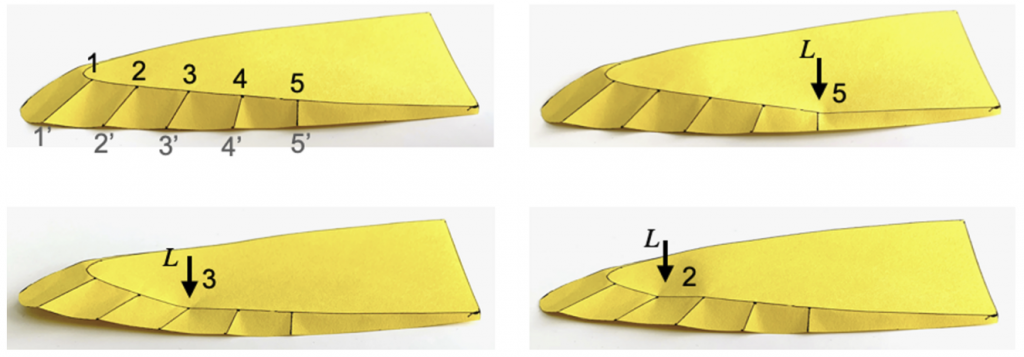
    Oriagmi analogue of an aeroelastic tymbal

    To understand this process, we studied the geometry and motion of the wing and then constructed a simplified creased-shell analogue, inspired by the mechanics of origami. The model captures how a thin shell with discrete crease-like features can buckle in a controlled sequence. In the moth, the resulting vibrations propagate into a nearby thin region of the wing, which acts as a lightweight radiating surface that emits sound.

    From a mechanics perspective, this is interesting because buckling is usually considered a structural failure. Here, however, it is deliberately built into the morphology and used as a functional mechanism. The ermine moth effectively couples the wing-beat motion during flight into a repeatable sequence of mechanical snap events that generate sound (and because the moth is deaf, it is none the wiser for it).

    Beyond the biological insight, this system highlights how thin shells with patterned creases can be designed to trigger controlled sequences of instabilities. Such ideas may be useful in the design of lightweight acoustic devices, responsive structures, or engineered systems that harness snap-through behaviour rather than avoiding it.

  • Model for kirigami buckling

    Model for kirigami buckling

    Kirigami is the sister of the more well-known origami. While origami focuses on creating art out of folding paper, kirigami extends this to allow for cuts to be introduced. Both origami and kirigami have been researched extensively over the last decade to explore potential applications in structural engineering.

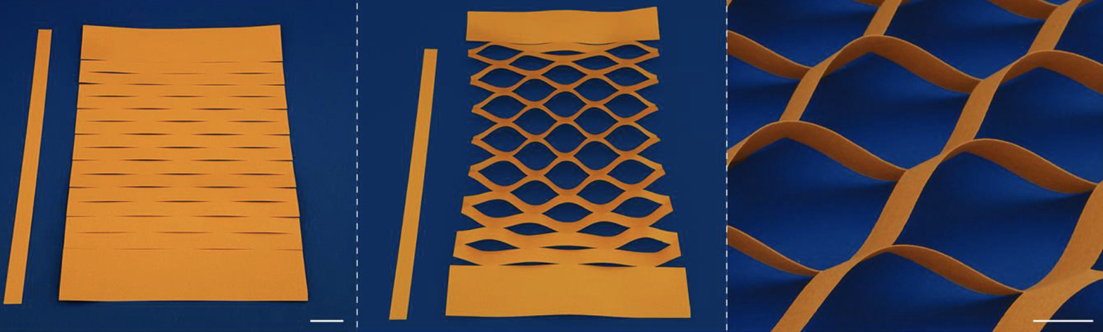
    For example, when a parallel matrix of cuts is introduced into a sheet of paper and that sheet is then tensioned, the cells between the cuts buckle out-of-the-plane to form a pattern. This effect is currently being used for expandable packaging but also to create lightweight tension springs for space applications.

    What is interesting is that depending on the ratio of cut length to vertical and horizontal cut spacing, different patterns can form. The cells either buckling anti-symmetrically, symmetrically or into a mixture of these two motifs (co-existence). These three behaviours lead to significantly varying tensional stiffness, which means that design approaches are needed to predict the buckling onset and stiffness correctly.

    left: symmetric mode; right: anti-symmetric mode; middle: co-existence

    To date, the three regimes have largely been explored using computational methods, e.g. finite element analysis. These methods are very accurate but tend to be slower than analytical methods and require designers to have access to sophisticated modelling software. In a recent publication, one of my PhD students (Yuwen Du) and I have introduced an analytical model that correctly predicts buckling loads as well as the buckling modes into the three possible configurations.

    With such a model it is now possible to rapidly design with this particular kirigami structure. In addition, the model has allowed us to delineate the energetic contributions that force the kirigami sheet to buckle into the anti-symmetric or the symmetric mode.

  • Gust load alleviation for aircraft wings

    Gust load alleviation for aircraft wings

    Aircraft wings are designed for the worst-case scenario encountered during a service lifetime. Generally, this is a severe gust that occurs only a handful of times but produces significant bending stresses at the wing root to require substantial reinforcement. Because the aircraft spends the majority of its lifetime not experiencing such a rare, extreme load case the wing is over-designed for much of its service life.

    The additional reinforcement and mass required to sustain these rare load cases unnecessarily increases fuel burn during standard operation (99.9% of the time).

    What if this extreme load case could therefore be removed from the aircraft’s life cycle?

    For example, by deploying a spoiler or tab into the airflow on the top wing surface to disrupt the boundary layer, detach the flow, and thereby dump lift and reduce bending moments at the root of the wing.

    Such a device is possible, but usually requires the integration of an active control system with sensors and actuators that also add weight and complexity to the structure and aircraft system. A more elegant solution is to use a passive device. For example, a structure that deforms as the wing bends during a gust and then triggers the spoiler to pop-out of the top wing surface. In a way, this would represent a “reflex” of the wing to protect itself from severe loading.

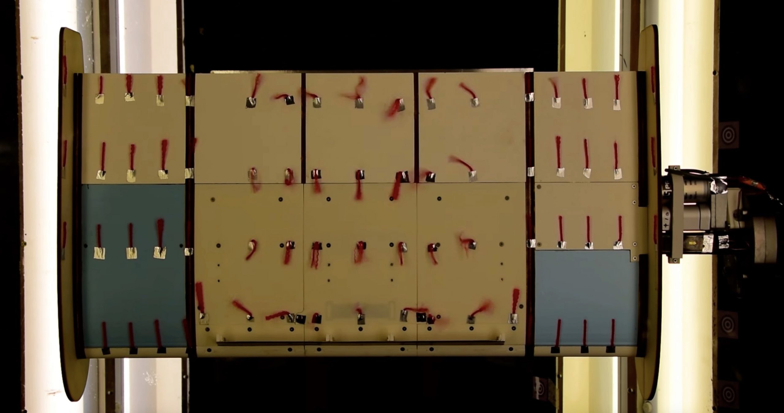
    In previous work, we (PhD student Ed Wheatcroft and Bristol colleagues Mark Schenk, Alberto Pirrera and I) designed such a device (1, 2) and tested its performance in a wind tunnel (see above image). These wind tunnel experiments proved the concept that a deploying leading-edge spoiler (albeit using an actuator in this proof of concept) could effectively reduce the lift produced by the airfoil.

    In our latest publication, the effectiveness of the spoiler is demonstrated on an aircraft-level study in collaboration with Airbus UK. To do this, an idealised full aircraft model was simulated and subjected to a number of different flight load cases, with the lift-reduction effect of the spoiler hard-wired into the simulation. The results demonstrated that the spoiler is capable of reducing the sizing wing root bending moment by up to 17% for the particular airframe considered.

    Following these promising results, the next steps are to integrate a spoiler into a flexible wing model that can then be tested live in a wind tunnel.

  • UKRI Future Leaders Fellowship

    UKRI Future Leaders Fellowship

    I am pleased to say that I have been awarded a Future Leaders Fellowship by UK Research & Innovation.

    The fellowship aims to demonstrate how lightweight and sustainable shell structures can be manufactured from reclaimed-fibre composites, accelerating the sustainable use of composite materials. To achieve this, the project will combine state-of-the-art manufacturing technologies and simulation tools across design and process simulation, and link key stakeholders along a new value chain.


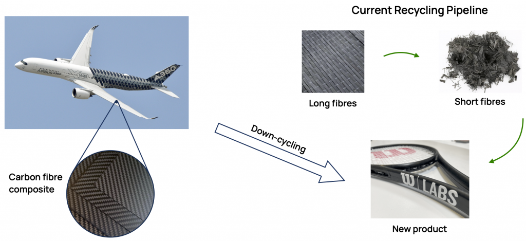
    Fibre-reinforced composites are used in many engineering applications where lightweight structures are needed. Composites are, however, currently deemed an unsustainable material choice for a circular economy owing to challenges around recycling. Existing recycling processes break the reinforcing fibres into shorter lengths, thereby leading to worse mechanical properties than the pristine material. As a result, recycled composites are currently used for predominantly low-value and non-structural applications.

    Current composites recycling value chain

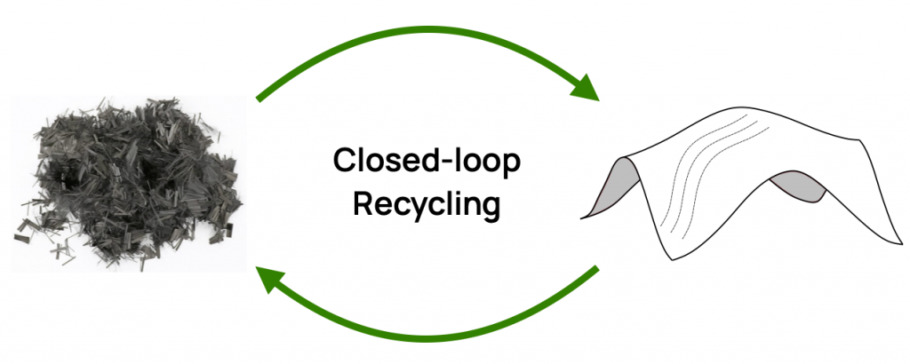
    The vision of my fellowship is to develop high-performance composite structures that are manufactured from recycled carbon fibre. This will be achieved by taking advantage of the unique processing benefits of short-fibre composites; in particular, the ability to form defect-free doubly curved shapes and the ability to easily steer the material along curvilinear trajectories. Using both computational design and automated manufacturing, my goal is to create ultra-lightweight structures that optimally combine geometry and material anisotropy.

    Several composite mega-structures are coming to the end of their planned service life. The current recycling approach is to either downcycle the embodied material into lower value applications or to bury the material in landfill. To prevent this terrible waste, new recycling approaches are acutely needed.

    By the end of the fellowship, my ambition is to have demonstrated the feasibility of an end-to-end value chain, ranging from material sourcing to a manufactured and tested structure with applications in high-value added industries such as aviation.

  • Multi-rotor wind turbines

    Multi-rotor wind turbines

    A PhD student I am co-supervising (Abdirahman Sheik Hassan) has just published his first paper—a review on multi-rotor wind turbines.

    To extract more and more energy from the wind, turbine blades are getting longer and longer. This scaling places significant challenges on the materials, manufacturing, testing, transportation, operation, and maintenance of the blades. With blades exceeding 100 m in length, glass-reinforced composites are increasingly being replaced with stiffer carbon fibre; the quality of resin infusion during manufacturing is increasingly difficult; and the transportation to the final site along roads is a major logistics operation.

    One possible solution out of this bottleneck is to locate multiple smaller rotors on a single supporting frame, a so-called multi-rotor system. Not only would this approach remove many of the challenges listed above around manufacturing and transportation, but it would theoretically allow the use of more sustainable bio-based composites whose inferior mechanical properties make them unsuitable for longer blades. In addition, analytical scaling arguments suggest that the cost of energy from multi-rotors decreases favourably with the number of rotors employed.

    Our review paper summarises the literature on multi-rotors from the past decades including aerodynamics, materials, structures, design, control, sustainability, reliability, and
    maintenance. The paper also highlights open questions around the environmental impact benefits of multi-rotors, the characterisation of rotor–rotor inter-
    action effects, and the investigation of aerodynamic noise, amongst others.

  • Prediction of dimple initiation site in shells using digital image correlation

    Prediction of dimple initiation site in shells using digital image correlation

    I have just published a new paper in the Proceedings of the Royal Society A with collaborators at IIT Hyderabad (India).

    Thin-walled cylinders are used in various engineering applications ranging from fuselages in aircraft to fuel tanks in launch vehicle stages. When thin-walled cylinders are compressed, they are susceptible to buckling and this occurs at loads well below what is suggested by analysis. As a result, cylinders are designed with very conservative safety factors.

    One way to improve the design process is to devise a non-destructive testing framework that can predict when a manufactured cylinder will buckle, which would then provide information on potential remedial measures. Such a methodology has recently been developed, where a cylinder is probed laterally from the side to measure its resistance to indentation, but the method is very dependent on the location of probing.

    Buckling of cylinders is a local event, where a single dimple initiates a dynamic buckling sequence. Probing should occur at the weakest spot where the dimple initiates. However, this site is not known a priori as it depends on imperfections in manufacturing and loading.

    Our paper showed that the dimple initiation site can be predicted from deformation measurements (using digital image correlation) before buckling occurs. The measured deformations are used to compute a bending energy measure which successfully reveals the presence of a developing dimple at approximately 60% of the critical buckling load.

    This information can help to determine where to probe the cylinder to determine the buckling load in a non-destructive manner, i.e. without ever pushing the cylinder to the buckling point.

  • BladeUp: an EPSRC Prosperity Partnership

    BladeUp: an EPSRC Prosperity Partnership

    Led by Alberto Pirrera at the Bristol Composites Institute, we’ve been awarded a Prosperity Partnership grant in collaboration with Vestas Wind Systems and LMAT.

    The BladeUp project will secure the upscaling of wind turbine blade production capacity to meet growing demand in clean wind energy.

    The project will transform the design and manufacture of wind turbine blades using advanced computer modelling and machine learning, thereby cutting costs, reducing waste and speeding up production to make wind energy more affordable and reliable.


    The push towards sustainable energy has increased the need for renewable sources likes wind power. Meeting this rising demand requires a scale-up in wind turbine production capacity while maintaining manufacturing quality. Some estimate a required tripling in global renewable capacity by 2030 to meet net-zero emission targets.

    Straight-forward approaches like building more factories to raise production are very expensive. In addition, quality production relies on a skilled workforce which is not abundant in the short term. Finally, increasing production speed is likely to lead to more defects with downstream effects on turbine lifespan and in-service repairs.

    A new approach is clearly needed to increase production while maintaining quality.

    The BladeUp partnership between the University of Bristol, Vestas and LMAT aims to develop a different approach based on the following objectives:

    • new turbine blade designs that are optimised for ease and speed of manufacturing
    • new turbine blade designs that are inherently tolerant to manufacturing imperfections and design uncertainty
    • devising new streamlined processes for “right-first-time” manufacturing at speed and scale

    We anticipate that addressing these goals will also have spillover effects into other industry sectors where composite materials are used at scale.