Martin Eichenhofer is the CEO & co-founder of 9T Labs, a company that was spun out of ETH Zürich in Switzerland. The company specialises in providing software solutions and manufacturing equipment for producing high-quality and high-performance composite materials using 3D printing.
By marrying the worlds of composite materials and 3D printing, 9T Labs is taking advantage of the superior material properties of composite materials and combining these with the geometric fidelity facilitated by 3D printing. As a result, components that were previously unfeasible to be manufactured using composite materials, either from a technical or cost perspective, are now within the realm of the possible.
What is unique about 9T Labs is that the company combines their hardware for 3D printing composite parts with a bespoke optimisation software in order to maximise a component’s performance, both in terms of structural design and manufacturing quality. Furthermore, it has been historically difficult to print continuous fibre composites at high quality with a low void content. 9T Labs, however, has patented a process that allows printing at a void content of below 1%, which competes with conventionally manufactured composites.
In this episode of the Aerospace Engineering Podcast, Martin and I discuss:
his background as an engineer and how his PhD research led to 9T Labs
the challenges and benefits of 3D printing composite materials
9T Labs’ unique approach to 3D printing composite materials
some of the applications the company is currently working on
Chris Voorhees is the founder and president of First Mode, a Seattle-based company that is designing and building technology for extreme environments off and on planet Earth.
Chris has decades of experience in the implementation of robotic systems for the exploration of deep space. His notable experience includes his work as a mobility systems engineer for NASA’s Spirit and Opportunity rovers and lead mechanical engineer for NASA’s Curiosity rover. For his efforts, Chris received NASA’s Exceptional Achievement and Exceptional Engineering Achievement medals.
Today, Chris oversees the design, development, and deployment of engineered solutions for missions around the globe and throughout the solar system. First Mode is also focusing on significant problems on Earth including the challenging issues of sustainability for the natural resources sector.
In this episode of the Aerospace Engineering Podcast, Chris and I talk about:
his background in engineering, including his time at NASA’s Jet Propulsion Laboratory
his past work on Mars rovers
why we should go back to the Moon
the space projects First Mode is currently involved with
and First Mode’s growing engagement in the hydrogen sector
Carl Copeland is the founder of Möbius Aero, an electric air race team, and MμZ Motion, a developer of custom, high-performance electric motors. Carl has built various engineering teams and led innovation in the fields of IT, mechanical, magnetic, and electrical design. He has founded four companies and holds over 25 patents, and his most recent innovation, the Field Modulation Motion System, is a novel electric motor design that is significantly lighter and smaller than established electric motors of similar power and torque ratings.
The Field Modulation Motion System achieves its high performance by using 18-phase field modulation rather than the three-phase modulation used in standard motors, essentially emulating six separate three-phase motors attached to a single shaft. Carl is putting his new engine design to the test in a new air racing series for electric aircraft known as Air Race E.
In contrast to typical air racing series, in Air Race E aircraft race against each other on a course rather than flying isolated time trials. In the past, air races have been an invaluable means of developing aerospace technology in a competitive setting and Air Race E is re-awakening the spirit of competition by launching the first fully electric airplane race series. In this episode of the Aerospace Engineering Podcast, Carl and I talk about:
his unique and auto-didactic background in engineering
his goal of finding practical solutions to humanity’s problems
the Air Race E competition and the origin story of Carl’s racing team Möbius Aero
the technical details and benefits of his new electric motor
Dr Evangelos Zympeloudis is the CEO and co-founder of iCOMAT, a company based in the UK that is developing automated manufacturing equipment for tow-steered composites. Fibre-reinforced plastics, such as carbon-fibre or glass-fibre composites, hold great promise for high-performance and lightweight design due to their excellent stiffness and strength properties at low material density. Traditional fibre-reinforced plastics are manufactured using straight uni-directional fibres or with straight fibres woven into a fabric.
Generally speaking, a fibre-reinforced composite derives its strength by aligning the fibres with the direction of the dominant load path. The novelty of tow-steered composites is that strips of composite material, so-called fibre tows, are steered along curvilinear paths such that the fibre direction is not straight, but varies continuously from point to point. This characteristic has benefits in structural design as the reinforcing fibres can now be used to smoothly tailor stiffness and strength throughout the structure. For example, tow-steered composites can be used to curve the reinforcing fibres around windows in an aircraft fuselage in order to improve strength and facilitate net-shape manufacturing.
In this episode of the Aerospace Engineering Podcast, Evangelos and I talk about:
his background as an engineer and entrepreneur
the manufacturing challenge of making defect-free tow-steered composites
the capabilities of iCOMAT’s rapid tow-shearing process
the benefits of tow-steering for manufacturing cost and design
and some of the projects iCOMAT is currently working on
Disclosure: I currently work with iCOMAT on a number of projects and am a consultant to the company.
Stefan Brieschenk is the Chief Operating Officer of Rocket Factory Augsburg (RFA), a company in the south of Germany that is developing a low-cost launch vehicle. RFA’s vision is to drastically reduce the cost of access to space through large-scale industrialisation of their operations and manufacturing.
Key to RFA’s design approach is a holistic performance and cost optimisation tool that has been developed in collaboration with space industry veterans MT Aerospace and OHB. This approach has led to interesting design choices. For example, the second stage tank is based on inexpensive stainless steel construction, and in places where composite materials are being used, RFA is relying on automotive grade materials that have already been used in high-volume production. In their propulsive system, however, RFA is chasing the highest performance—a closed-cycle staged combustion engine, enabled by modern manufacturing capabilities in 3D printing and which is due to be hot-fired early next year.
In this episode of the Aerospace Engineering podcast, Stefan and I talk about:
Stefan’s passion for rocketry and hypersonic flight
Dr Sanjiv Singh is a research professor at the Robotics Institute of Carnegie Mellon University and the CEO of Near Earth Autonomy. Sanjiv has more than 30 years of research experience in the field of autonomous vehicles and has spun-out multiple companies from his university research.
His current venture, Near Earth Autonomy, develops technology that allows aircraft to autonomously take-off, fly, and land safely, with or without GPS. Near Earth’s goal is to develop complete autonomous solutions that improve efficiency, performance, and safety for aircraft ranging from small drones up to full-size helicopters. The team at Near Earth was awarded the 2018 Howard Hughes Award, which recognises outstanding improvements in fundamental helicopter technology, and was also a 2017 finalist for the Collier Trophy, one of the most important aviation awards worldwide. In this episode of the Aerospace Engineering Podcast, Sanjiv and I talk about:
his background as a researcher in the field of robotics and autonomy
the fundamental concepts of autonomy
the hardware and software that make it work
the successful helicopter technology demonstrator Near Earth Autonomy has developed
In this episode I am speaking to Aaron Daniel and Peter Shpik of Alpine Advanced Materials. Alpine Advanced Materials specialises in the design and manufacture of custom-engineered parts and products for demanding aerospace and energy applications. The company is currently commercialising a high-performance material known as HX5™, which is a thermoplastic nanocomposite originally developed by Lockheed Martin Skunk Works® over a decade of testing and validation.
HX5™ was originally developed to replace aluminum at half the weight but with the same strength and stiffness. On top of that HX5™ has excellent durability in harsh environments such as in outer space, in radioactive settings or around aggressive chemicals. As a result, this new nanocomposite material is already being used on jet fighters, high-speed helicopters, UAVs, rockets, and satellites. In this episode of the aerospace engineering podcast Aaron, Peter and I talk about:
the importance of lightweighting in the aerospace industry
Norris Tie is the CEO of Exosonic, a California-based startup that is developing a low sonic boom supersonic passenger aircraft. Norris holds an engineering degree from UCLA, an MBA from Stanford, and before starting Exosonic worked on supersonic aircraft at Northrup Grumman, Virgin Galactic and Lockheed Martin Skunk Works.
What differentiates Exosonic from other upstarts in the reviving supersonic aircraft space is that the company is specifically focusing on reducing the intensity of sonic booms. Current regulation forbids supersonic flights across America to minimise noise pollution; a restriction which significantly limited the routes that the first supersonic airliner, the Concorde, could fly. To soften sonic booms, Exosonic is using a concept and technology originally pioneered by NASA known as shaped sonic booms. As a first step, Exosonic has partnered with the US Air Force to develop a supersonic executive transport aircraft that will provide US leaders and diplomats rapid transportation around the world. In this episode of the Aerospace Engineering Podcast, Norris and I talk about
his life-long inspiration for speeding-up air travel
the theory behind shaped sonic booms
what is different about designing supersonic aircraft
Euan Wielewski is the co-founder and CEO at Anomalous Technologies, a start-up based in Edinburgh, Scotland using the latest machine learning and artificial intelligence (AI) technologies to enable better quality control of manufactured components.
As aerospace engineers we know that quality control and inspection of flight-critical hardware is essential to guarantee safe operation of aircraft. Human visual inspection is a subjective and analogue process, which means that flight hardware is typically double and triple-checked to high levels of accuracy. This is where the AI tools developed by Anomalous Technologies are invaluable. By making inspection digital, operational traceability is immediately enhanced. Furthermore, digitisation allows the human inspection process to be accompanied by statistical tools that reduce the error rate of missed defects and improve inspection efficiency.
Anomalous are already working with global aerospace companies such as Rolls Royce and Boeing, and the company is currently a member of the first cohort of the ATI Boeing Accelerator. In this episode of the podcast, Euan and I talk about:
his broad background in aerospace engineering
the challenges of human inspection in the aerospace industry
how data-centric methods such as AI tools can help improve inspection accuracy and efficiency
and how Anomalous is using their analytic tools to help out in the current Coronavirus pandemic.
This is the second guest post by Jason D’souza, a recent MSc Graduate in Aerospace Vehicle Design from the University of Cranfield in the UK. Winglets are aerodynamic devices that feature on many modern commercial aircraft, but do have certain drawbacks. In this post, Jason considers a slightly different, on-demand system, known as a fluidic winglet and demonstrates its interesting properties using CFD analyses.
Turmoil in The Sky
The environmental impact of aircraft carbon footprint is of rising importance to all operators as consumer demand for air travel continues to grow. The aviation industry holds a small contribution to global emissions, but unequivocally, it is one of the fastest growing contributors to emissions. Since the 1970s, when the price of aviation fuel began to spiral upward, airlines and aircraft manufacturers have explored many ways to reduce fuel consumption by improving the operating efficiency of their aircraft. Fuel economy concerns have been particularly important for operators of commercial aircraft, which typically fly many hours per day in competitive markets. Hence, there are also good economic incentives for reducing emissions, since reduced emissions are naturally related to reduced fuel consumption and savings in fuel expenditure for air carriers. A great potential source for fuel savings is reducing parasitic drag of the airframe, such as inherent wingtip vortices.
Introduction to
Wingtip Vortices
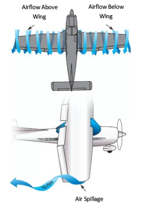
Wingtip vortices are schematically illustrated in Figure 1. If a wing is producing lift, a pressure differential exists between the upper and lower surfaces, i.e. for positive lift, the static pressure on the upper surface will be less than on the lower surface. At the tips and trailing edges of the wing, the existence of this pressure differential creates a vortex where the high-pressure air below the wing spills onto the low-pressure area above the wing to form a swirling tunnel of turbulent air along (top of Figure 1) and behind the wing (bottom of Figure 1). The vortex is strongest when the angle of attack is high, such as during take-off and landing, because the pressure differential at high angles of attack is greatest during these phases.
Why are wingtip vortices detrimental to
aircraft aerodynamics?
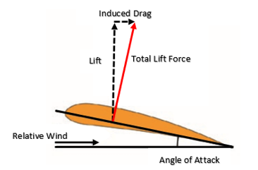
To create a specific lift coefficient with the airfoil section, a certain angle of attack must exist between the airfoil chord line and the relative wind; see Figure 2. However, as the total lift force is developed perpendicular to the wing chord line, it is angled slightly backwards. There are two problems occurring here; firstly, some of the total lift force is now deflected backwards leading to the creation of lift-induced drag, illustrated in Figure 2; and secondly, there is a smaller component of lift pointing upwards to counterbalance the weight of the aircraft. Both of these effects are to the detriment of the lift-to-drag ratio, a key efficiency parameter in aircraft design. Thus, as a result of this decrease in vertical lift, the wing must be given an angle of attack greater than the current section angle in order to generate more lift to account for the inclination of the total lift force. However, any increase in the angle of attack also increases the lift-induced drag. Wingtip vortices exacerbate this lift-induced drag by causing the total lift force to point even further backward. A number of possible solutions exist for mitigating the effect of vortex-induced drag, but conventionally, wingtip retrofits, commonly known as winglets, are used to mitigate the problem.
Figure 2: Lift-Induced drag.
How do winglets
help to improve the situation and what are some of the drawbacks?
One of the visible
actions taken by commercial airframe manufacturers to reduce wingtip vortices
is the modification of an aircraft’s wingtip by installing, as shown in Figure 3,
near-vertical “winglets”. Experience shows that these tip devices reduce block
fuel consumption (total fuel burn from engine start at the beginning of a
flight to engine shutdown at the end of the flight) of the modified aircraft by
3% – 5%, depending on trip length [1].
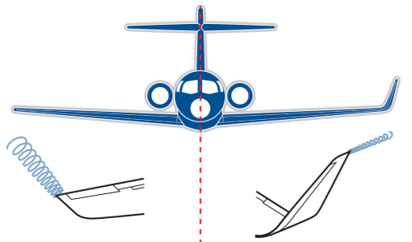
Figure 3: Vortex intensity with and without winglets [3].
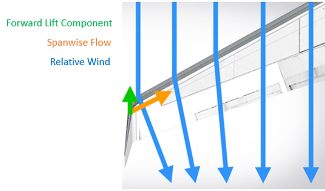
Winglets are airfoil-shaped
structures that also produce lift but are orientated inwards towards the
fuselage relative to the rest of the wing. The presence of winglets changes the
effect that wingtip vortices have on lift and drag. The winglets cause the
relative wind to bend inwards towards the fuselage, creating a forward vector
of lift in the direction of flight counteracting some of the induced drag, as
illustrated in Figure 4.
Figure 4: Creation of forward lift force to partially alleviate induced drag [4].
However, winglets do not operate effectively under all conditions throughout the flight envelope and incur an added mass penalty. So, the question is whether winglets conserve more fuel by reducing drag than the extra fuel required to carry their mass? An inherent problem with winglets is their susceptibility to flutter and increased bending stresses in the winglet fold area. In fact, under some flight conditions an equal area, flat span extension can be a more effective and less risky design solution. Lastly, winglets are always present in flight, as they are fixed devices attached to the tips of wings, and because they are fixed surfaces, they provide their best lift-induced drag reduction for a single design point. Hence, a more on-demand and active, rather than passive, type of control device could be of benefit. One example is the use of a “Fluidic Winglet”.
What is a fluidic winglet and how does it work?
A fluidic winglet is a
system architecture that can provide a controlled stream of air ejected outwards
in the vicinity of the wingtip, as shown in Figure 5, to create an aerodynamic
force strong enough to disrupt the vortex formation. This system architecture
could potentially produce the same benefits as a winglet without a visible increase
in wingspan.
Figure 5: Wing with fluidic winglet.
The pressurised air for the fluidic winglet could be taken from:
The jet engine
The aircraft surface
The leading edge of the wing
An internal pressurised air tank
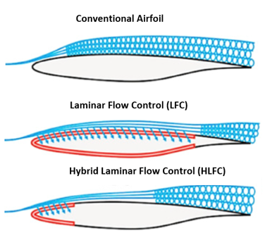
RAM drag (a common source of system-induced drag caused by taking in air, typically for cooling purposes) and weight penalties introduced from the above systems must be considered when evaluating the system. If air is taken from the aircraft surface, then a Laminar Flow Control (LFC), a Hybrid Laminar Flow Control (HLFC) system, or a duct located at the wing leading edge stagnation pressure line could be appropriate. However, this would not result in high jet momenta and will be limited to lower mass flow rates [5]. The LFC and HLFC systems are active boundary layer control techniques, shown in Figure 6, that help to maintain the laminar flow state by means of suction onto the wing surface during flow states that would otherwise be transitional or turbulent.
Figure 6: Laminarisation of flow using LFC and HLFC systems [6].
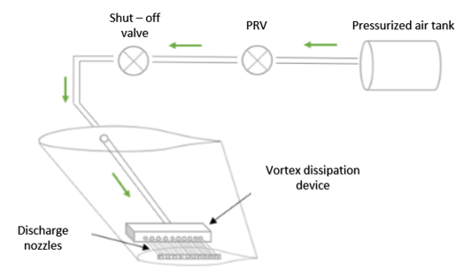
If the air used to
operate the fluidic winglet is taken from a separate pressurised tank inside
the fuselage, the fluidic system could look something like depicted in Figure 7.
Once the pilot signal is received, a solenoid valve allows the air to be
released from the tank where it is regulated to provide the required exit
velocity. The air then flows into the vortex dissipation device where the air
is distributed to the discharge nozzles. If the exit pressure past the pressure
regulating valve (PRV) exceeds the design limit, a shut-off valve ahead of the
PRV will not allow fluid to pass above a certain set pressure as a fail-safe.
Figure 7: Potential fluidic system architecture.
Analysis – What potential benefits of the fluidic winglet can be expected over conventional alternatives?
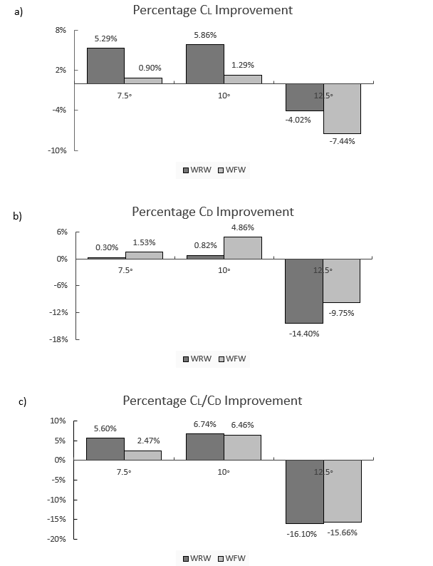
In order to ascertain the potential benefits of the fluidic winglet, the lift coefficient (CL), drag coefficient (CD) and lift-to-drag ratio (CL/CD) of three models are investigated using ANSYS Fluent, and the results are extracted and summarised in Figure 8. The models designed are:
A clean wing (CW) with no winglet attached: designed from a NASA HSNLF (1)-0213 airfoil with a leading-edge sweep angle of 33° and a taper ratio of 0.4.
A wing with a raked winglet (WRW): designed from a NACA 0012 airfoil with 10% of wing semi-span and a taper ratio of 0.2 and with a sweep angle greater than that of the wing of about 57°.
A wing with the fluidic winglet (WFW): this will not require a wingtip extension, and hence, there is no physical increase in the wing’s span. The fluidic winglet instead consists of a rectangular high-aspect ratio slot.
Note: The models do
not have an aerodynamic twist consideration.
The boundary conditions that constitute the flow variables are: a freestream velocity of 50 m/s and an injection velocity three times the freestream (150 m/s) with a jet sweep angle equivalent to that of the wing sweep (i.e. the jet is co-linear with the wing). These models will be tested at high angles of attack of 7.5°, 10° and 12.5° to simulate the effect of the fluidic winglet on the vortex when it is strongest.
Figure 8: a) Lift coefficient improvement with addition of raked and fluidic winglet. b) Drag coefficient improvement with addition of raked and fluidic winglet. c) Lift-to-drag ratio improvement with addition of raked and fluidic winglet.
As illustrated in Figure 8c), the results indicate that having a tapered wingtip extension (i.e. a raked wingtip, WRW) provides improved aerodynamic efficiency (CL/CD) of 7% for an angle of attack of 10°, and generally better levels of drag reduction are expected at lower (7.5° and 10°) angles of attack than higher (12.5°) angles. As shown in Figure 8a), the WRW improves the lift coefficient much more than the fluidic wingtip (WFW). This is due to the increase in wing area added by the physical wingtip. However, this additional surface area causes a parasitic component of drag, which is why the WFW outperforms the WRW design in terms of drag coefficient, as shown in Figure 8b). Further, in Figure 8c) it appears that the WRW’s performance is reduced by 16% at an angle of attack of 12.5°, which occurs due to local wingtip stall. There are two reasons for this stall occurrence; firstly, the dissimilarity between the main wing airfoil and the raked winglet airfoil and secondly, the WRW is not twisted. The WRW should employ twist to avoid local stalling at such high angles of attack.
Similarly, the application of the fluidic WFW at high angles of attack leads to improvements to the wing’s aerodynamic efficiency. As shown in Figure 8c), at 7.5° angle of attack, the lift-to-drag ratio is increased by 2.5%, and at 10°, the lift-to-drag ratio is increased by 6.5%. However, for the 12.5° angle of attack, when the 50 m/s freestream air collides with the 150 m/s jet, stalling occurs locally, thus spoiling the lift and increasing drag. This stall condition occurs due to a local increase in the Reynolds number in the region where the freestream and jet efflux meet.
Nonetheless, because the fluidic winglet has no additional surface exposed, there is no increase in parasitic drag. This fact contributes to acceptable drag reductions as shown in Figure 8b). Hence, the overall enhancement of the lift-to-drag ratio between the WRW and the WFW is very similar emphasizing the capability of the WFW. The WRW is more effective at improving the lift, whereas the WFW is better at reducing drag. Furthermore, the WFW can be activated at any specific angle of attack, and has the potential to deliver better levels of drag reduction at more than a single design point during the flight envelope. Other benefits not only include potential improved fuel economy, but also improved payload-range capability, improved take-off performance, and less take-off noise.
How is the fluidic
winglet able to improve the lift-to-drag ratio?
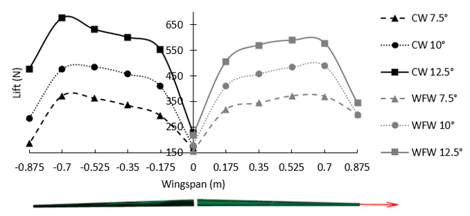
The WFW is able to improve aerodynamic efficiency by altering the chordwise lift distribution along the wingspan. It is generally well known that an elliptical lift distribution in the spanwise direction is optimal for reducing induced drag for a specific wing area and lift. First, as shown in Figure 9, the WFW (right figure) makes the lift distribution more elliptical than the clean wing (left figure). Furthermore, it is observed that, at high angles of attack, the sectional chordwise pressure distribution on the upper and lower surface of the WFW changes favourably from root to tip.
Figure 9: Spanwise lift distribution over CW (Left) and WFW (Right).
The spanwise variation in the sectional lift force, as shown in Figure 9, for the CW is observed to increase until the 80% wing semi-span location, at which point it drops off dramatically. This drop off in lift force towards the wingtip (100% wing semi-span position) is due to the creation of wingtip vortices that disrupt effective lift generation over the wing. It is clear that the aerodynamic lift force is considerably increased by the WFW towards the wingtip for the 7.5° and 10° conditions, thereby demonstrating the effectiveness of the jet efflux to increase the aerodynamic loading at the wingtips for the angles of attack tested herein. The only exception is the 12.5° angle of attack condition, where the addition of the fluidic jet efflux creates a local stall condition, as previously discussed above.
Additional thoughts
– How could fluidic winglets be implemented?
It is important to
evaluate aircraft inventory and identify the most suitable aircraft candidates
for fluidic winglet modification. The process could be summarised under four
main tasks:
Examine the feasibility of modifying aircraft with fluidic winglets, to include a cost-effectiveness analysis of the modification in net present value (NPV) terms.
Determine the market price of aviation fuel at which incorporating the fluidic winglets would be beneficial for each platform.
Consider impact to aircraft maintenance and flight operations (including ground operations).
Investment strategies to minimize the operator’s capital investment and maximize investment return.
These tasks call for a
quantitative assessment of the costs and benefits of fluidic winglet
modifications on a variety of platforms. In a comprehensive analysis, one would
need to include the non-recurring engineering costs of wing analysis and
fluidic system design, as well as the costs of materials, manpower, and
out-of-service time to accomplish the modification, financial implications,
training costs, potential impacts on maintenance docks, costs associated with
software and technical manual revisions, and any impacts on maintenance,
operations, or mission accomplishment.
In each case, the
aircraft structure needs to be studied and determined to be appropriate;
engineering design must be analysed in detail; modifications will need to be
prototyped, tested, and certified; modification kits to be developed and flight
manuals revised as required. Past commercial experience with aircraft that have
installed conventional winglets has shown that there have been no significant
impacts on aircraft maintenance, flight operations, or ground operations (gate
space, taxiways, hangars, etc.) [1].
Conclusion
It is clear that aerodynamic improvements, including fluidic winglets, can make significant contributions to the efficiency of aircraft. In each case, however, the appropriateness of such structural/system modifications must be determined fleet by fleet. These decisions are very complex and will depend on many factors, including the design of the aircraft’s structures, systems design, design margin within those structures, the condition of the structures, mission profiles, utilisation rates, fuel consumption rates, fuel prices, and the remaining life of the aircraft. There are also other ways to reduce fuel consumption, many of which have already been adopted by commercial airlines. Nonetheless, the best solution is decided by economics rather than aerodynamics.
The design of the
fluidic winglet combines several disciplines such as structures, manufacturing
and assembly, systems, aerodynamic and flight dynamics. The selection of the
most appropriate system air resource and subsequent system design will depend
upon the jet efflux requirements of the fluidic winglet. The benefits of the
concept are highly dependent upon the jet parameters like the jet momentum
coefficient, jet dihedral, jet sweep, jet thickness and jet area as well as the
boundary conditions. Higher jet momenta and smaller jet cross-sectional areas
show promise to move the vortex centre further away from the wingtip to
increase the effective wingspan. Jet sweep angles higher than the wing sweep
angle are not suspected to provide improved results.
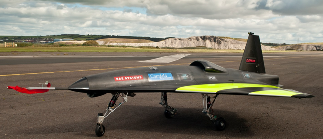
Figure 10: Flaviir demon project – a collaboration between BAE Systems and Cranfield University [7].
Since 2010, BAE
Systems has set out to develop key technologies and skills with long-term
collaboration from academia, industry and the UK government to create the
combat air system of the future so that the UK can deliver more advanced
capabilities through shared investment and revolutionise aircraft design. The
first ever exhibit of fluidic flight control (i.e. no flaps, elevators or
ailerons) begins with the FLAVIIR Demon Project (Flapless Air Vehicle
Integrated Industrial Research program), a UAV showcasing new technology for
the conventional flight control system. There are slots located on the wing’s
trailing edge for the blown compressed air taken from the APU (Auxiliary Power
Unit) to be curled either upwards (i.e. lowering the wing) or downwards (i.e.
lifting the wing) to provide for control of the aircraft. This allows for a
more seamlessly integrated design with fewer mechanically moving parts, and
hence, a design with reduced edges and gaps that make the aircraft less
observable on radar.
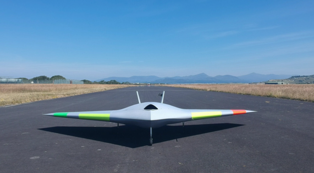
Figure 11: MAGMA project – a collaboration between BAE Systems and the University of Manchester [8].
Similarly, in 2017 BAE
Systems, in collaboration with the University of Manchester, revealed the first
flight of MAGMA, a new UAV iteration showcasing novel control technologies for
wing circulation control and fluidic thrust vectoring. The wing circulation
control system takes air from the aircraft engine and blows it supersonically
through the trailing edge of the wing to provide roll control for the aircraft.
The fluidic thrust vectoring systems also uses blown air to deflect the main
thrust allowing for the pitch direction of the aircraft to be changed. So far,
flight tests have been promising and we are awaiting the first use of such circulation
control in flight on gas turbine aircraft.