Category: Composite Materials

  • A Vision for Shape-Adaptive Aircraft

    Over the last couple of months, a number of readers of the blog and listeners of the podcast have asked me about my research. Although there is a brief overview on the Research page, the information there probably leaves too many things unsaid to form a clear picture of what we trying to achieve. On the other hand, going into the nitty-gritty details of the mathematical models, computer methods and prototypes that we are developing will probably bore most readers of this blog senseless. In fact, communicating the technical details of research is often counterproductive when creating awareness with colleagues, the general public and funding bodies.

    The power of stories

    A much more effective way of communicating one’s ideas is through stories. For many centuries, stories were the predominant means of understanding life and society. Orators, poets and philosophers used analogies, metaphors and fables as arguments that voiced something important about reality. In this way, literature is not mere wordplay, but an effective means of communicating a complex topic in a manner that sticks, often with recourse to emotion. There is even evidence to suggest that stories have evolutionary utility, by being a means to relay important information such as a lucrative hunting spot. This hypothesis would suggest that a proclivity for stories is hardwired into our psyche. Some people, like Jonathan Gottschall, even argue that we live our entire lives by projecting a web of stories over everything we perceive through our senses.

    In many ways, the great achievement of the Enlightenment, and Western thought in general, is a devotion to rationality: I don’t want to hear the story, give me the numbers instead. In his biography of Steve Jobs, Walter Isaacson argues that rational thought is not an innate human characteristic as such, but rather needs to be learned. Engineers—at least the good ones—should have plenty of this training. And perhaps this training is why we generally have a hard time communicating our ideas through stories—sticking rather to the technical details, which, generally speaking, tend to be a lot less inspiring.

    Taking inspiration from nature: shape-adaptation

    So what I will attempt to do in this post is to relay some of the technical details of our research through a vision of the future—a story of science-fiction if you will. It is a vision of shape-adaptive aircraft that can radically re-configure their shape as the operating conditions around them change.

    Engineering systems are typically designed to meet multiple specifications stemming from (i) different functions that the system is meant to fulfill and (ii) the broad spectrum of environments it is operating in.

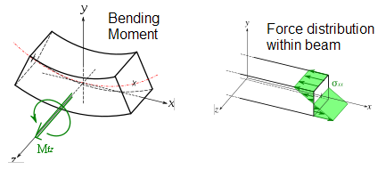
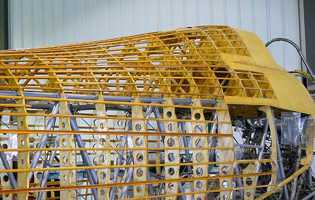
    In terms of functionality, the most efficient approach is combining as many functions into one system as possible—so-called multi-functionality. For example, the wings of early aircraft such as the Wright Flyer, had two mechanisms for resisting aerodynamic loads and providing lift. The strut-and-wire-braced box truss provided bending rigidity and torsional stiffness against excessive wing bending and wing twisting, while the fabric wing skins provided the aerodynamic profile. The structural and aerodynamic functions were separated into two systems, and neither contributed to the other. In modern, stressed-skin designs, the externally visible wing skin serves both as an aerodynamic profile and also provides structural support.

    Wright brothers patent plans 1908

    When the operating conditions around an aircraft change, the situation is a bit more complicated. In isolation, different conditions can push the design in opposite directions, meaning that some form of design compromise is needed. The disadvantage of a compromise is that the aircraft will perform sub-optimally in most, if not all, of the individual operating conditions.

    A solution to this conundrum is adaptation, also known as morphing, which would allow structures to change geometry and/or material properties in response to changing conditions. As with many good ideas we can take inspiration from nature. For example, birds can adapt the camber and angle of attack of their wings to react to different flight conditions. On modern aircraft wings, leading-edge slats and trailing-edge flaps, which are used to increase the lift-generating capabilities of wings at slow airspeeds, crucial for landing and takeoff, are manifestations of such adaptation. Even though these devices are effective and reliable, they rely on ancillary devices, such as heavy hydraulic or electric actuators, to facilitate the wing shape adaptation. By flexing and relaxing their wing muscles, birds have the ability to adapt between many different wing configurations, and due to the information-processing capability of the nervous system, this happens quickly and on the fly.

    Voilure A319

    Hence, the challenge for engineers is how to embed shape-adaptive technologies in a multi-functional manner. And ideally, we would want both the actuation (think muscles), sensors (think nerves) and information processing (think brain) to be integral to the materials or structure. Only in this way will it be possible to design seamless and aerodynamically efficient aircraft that have the ability of sentient organisms to adapt to a wide array of changing environments.

    An historic aside

    The biomimetic inspiration for morphing and adaptive technologies has been around since the dawn of powered flight. This is no surprise given that many of the early aircraft pioneers took their inspiration from nature—dissecting bird wings and observing birds in flight to borrow ideas for steering and control. For example, the Wright Flyer used flexible wingtips that could be warped using pulleys and cables. Even though this technique became known as wing warping, it is essentially a basic form of wing morphing.

    WrightBrothers1899Kite


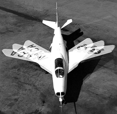
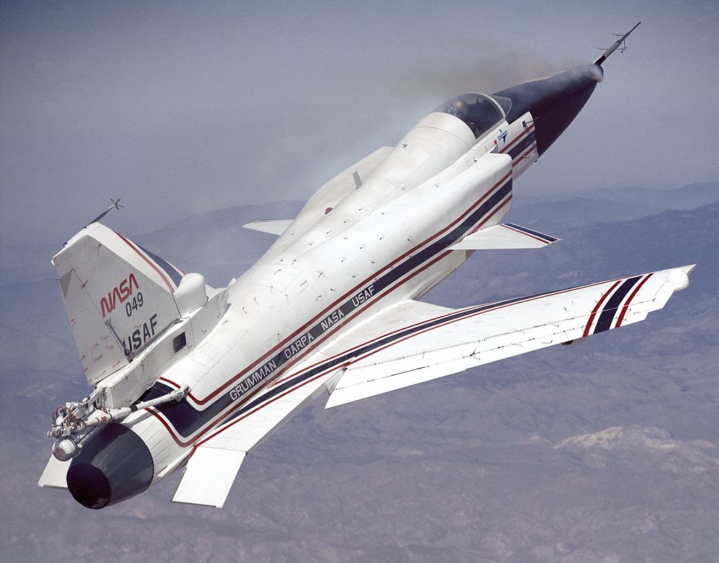
    In the 1910-1920s many patents about variable camber wings, telescopic wings and variable angle-of-attack wings were filed, but none of these concepts made it into production. This can partly be explained by the shift from a more compliant timber and fabric construction to a stiffer metallic design. This allowed for greater flying speeds and bigger aircraft, but increased the energetic threshold required for shape adaptation. Interest in morphing aircraft intensified in the post-WWII era, when the technological race between the USA and the USSR provided the impetus for many novel ideas. One example, the Bell X-5, featured variable wing sweep in flight. Wing sweep reduces the effective airspeed across the lifting surface and can therefore be used to prevent supersonic shocks—a source of parasitic drag. The faster you want to fly, the greater the required sweep, and hence this adaptive feature allowed the X-5 to fly more efficiently at subsonic and supersonic speeds. The same concept was successfully implemented in the MiG-23, Grumman F-14 and Rockwell B-1B. Apart from moving slats, flaps and control surfaces present on most aircraft today, the most prominent modern example of morphing is probably the drooping nose of the Concorde, which was used to find a compromise for better cockpit visibility during landing and streamlining at cruise.

    These early morphing ideas revolve predominantly around mechanically operated devices. That is, multiple components are joined by a mechanical hinge and the different components are then moved relative to each other by an actuator. Starting from the 1990s, new developments in materials science catalysed a shift from mechanical devices to novel materials. For example, during the late 1990s NASA Langley and DARPA led the Morphing Project and Smart Wing programme, which led to wing prototypes with gapless and hingeless leading- and trailing-edge control surfaces. NASA also released its now renowned artist impression of a morphing aircraft set in the year 2030, with wings that are capable of sweeping back and forth, changing shape and with compliant feather-like control surfaces for extreme manoeuvres.

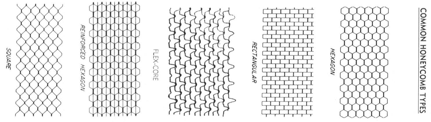
    Over the last 20 years, lots and lots of different materials have been used for a range of morphing technologies and concepts. Many of these technologies, ranging from flexible elastomers and honeycomb-type auxetic materials, to deployable structures and shape-memory metals, are summarised in the excellent review paper by Thill et al. from 2008. One particular concept, the FlexSys Mission Adaptive Compliant Wing (MACW), which has a moveable internal structure covered by a flexible skin and is capable of morphing the trailing edge through an angle of 20°, has been undergoing extended flight tests. One of these tests on the Scaled Composites SpaceShipOne suggests that the MACW could lead to 15% in fuel savings due to an improved laminar flow profile and minimal flow separation.

    A shift in perspective: Well-behaved non-linearity

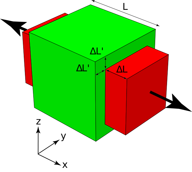
    To most engineers, non-linearity is something to avoid. In a linear system, cause and effect are proportional—if I apply a force of 100 N to a beam and it bends by 1 mm, then I can expect it to bend by 2 mm for a force of 200 N and 4 mm for a force of 400 N. What is more, for a more complex situation with many interacting parts, a linear system is always a simple addition of its parts. This means a multi-part system can be broken apart, its constituents analysed individually, and the behaviour of the whole system deduced from an aggregation of the constituents. This linear decomposition is not possible for a non-linear system, which means that (i) non-linear systems are more complicated and costly to analyse, and (ii) the non-linearity can lead to unwanted and counter-intuitive effects.

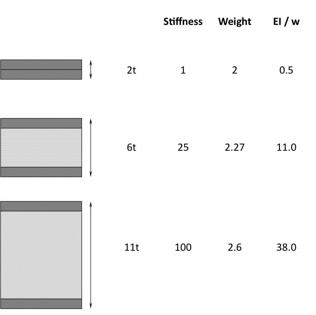
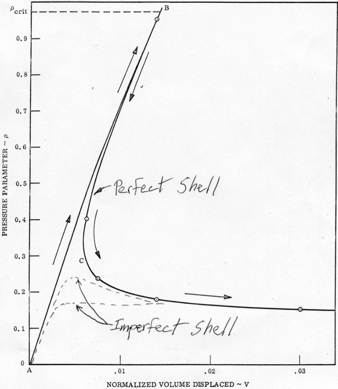
    One example of structural non-linearity is an instability. In aerospace engineering, minimising mass is the main design driver for more efficiency. No matter if you are trying to hold an aircraft aloft or shooting a rocket into space, the lighter your machine, the easier your task. This drive for lightweighting leads to thinner and thinner structures, where instabilities (like buckling) play a greater and greater role. In general, buckling is the tendency of thin-walled structures (struts and plates) loaded in compression to spontaneously bow out-of-plane (bend) at a critical value of compression. The buckling load varies with the cube of the strut’s or plate’s thickness, and while minimising thickness is very effective for reducing mass, it means that the susceptibility to buckling shoots up very quickly. Buckling is a non-linear event because the structure fundamentally changes its deformation mode—from one involving only compression, to one involving bending. Because there was no bending component pre-buckling, the bent post-buckling state cannot be a simple aggregation of pre-buckled states, and hence the phenomenon must be non-linear.

    Buckled column

    In traditional engineering design, buckling is considered as an unwanted “failure” mode to be treated no differently than material fracture, fatigue or plastic deformation. This traditional view is for good reason because buckling can cause a structure to lose its stiffness, and in the worst case, collapse. However, seen in a different light, the change in deformation mode brought on by buckling, can also be viewed as an opportunity for well-behaved shape-adaptation.

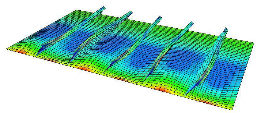
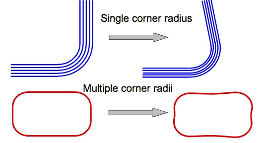
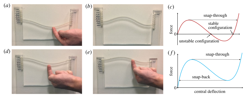
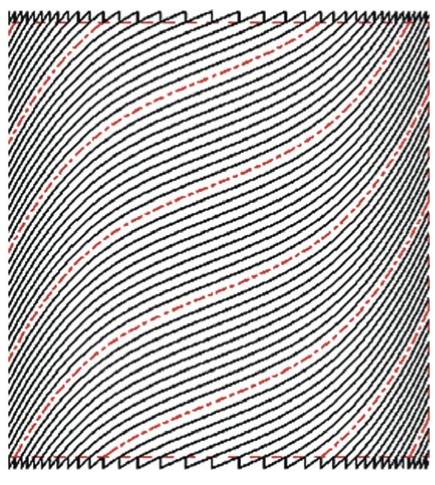
    This concept can be illustrated using an example that will be familiar to most people who have sat through an introductory mechanics course as an undergrad—the Euler strut pictured above. Take a thin strut and pin the two ends so that they cannot move perpendicular to the strut axis. Then apply a compressive load by moving the two ends closer together. For an idealised strut with no geometric imperfections and with the load perfectly aligned with the strut axis, the strut will remain flat and simply compress. At a critical value of the applied load, the strut will suddenly bow out-of-plane, i.e. bend into one of two mirror-symmetric sinusoidal shapes. By applying a load perpendicular to the strut axis, the structure can now be snapped from one sinusoidal shape to another. This is indeed a pronounced snap, whereby the strut needs to be actively pushed in the direction of the other shape, but once a critical point is reached (a so-called tipping point), the strut suddenly and automatically transitions to the other shape without any further expenditure of energy. And once the load is removed, the structure will happily stay in this second configuration.

    Limit point instability

    This is known as as bi-stable structure because there are two distinct configurations, which are both stable under no applied transverse load. These bi-stable systems are attractive for shape-adaptation, because to facilitate the shape change, energy only has to be expended to reach the snapping point, and thereafter the structure will happily settle into the second configuration.

    Of course, this system is rather simple and these two sinusoidal shapes are not directly useful for the large spectrum of shape-adaptations we would want to achieve for real aircraft structures. However, even for this simple example, the design space is relatively large because the two strut ends can be moved or rotated relative to each other such that the initial shape of the strut is no longer flat but curved. In this manner, a wide array of different configuration pairs is attainable. Furthermore, by varying the degree of compression the post-buckled strut can be designed so that one of the two configurations is unstable if the snapping load is removed. This means that the structure can be snapped from an initially curved shape into another, and when the transverse load is removed, the strut will automatically snap back to its previous shape. This is generally known as a monostable snapping device.

    Multistability and snap-through. (a) The application of a transverse load causes snap through into the inverted stable shape (b). (c) The applied load increases until it reaches a critical value. At this point, the beam snaps through a region of instability, where applied load decreases, reaching a second stable branch. Upon load removal, the structures settles in the secondary stable state. Similarly, a monostable buckled structure snaps from its first (d) to its second inverted configuration (e) when a transverse load is applied, but, as shown in (f), load removal causes snap back to the original unloaded equilibrium (d). Reproduced from Arena et al. (2017) Adaptive compliant structures for flow regulation. Proc.R.Soc.A 473: 20170334

    Hence, from these general concepts illustrated via a small toy model, it follows that it is possible to take advantage of concepts such as bi-stability and snap-through instabilities to induced repeatable and well-behaved shape changes.

    An example: a shape-adaptive air inlet

    The multi-stable behaviour described above can, for example, be used to design an adaptive air inlet for engine cooling on car bonnets or jet engine covers. In this situation, you generally want the air inlet to be open at low velocities to maximise the air flow into the engine. At higher velocities, however, enough air is impinging onto the hot parts of the engine that these additional cooling ducts can be closed to reduce the induced drag.

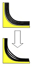
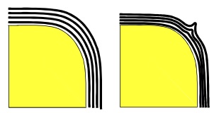
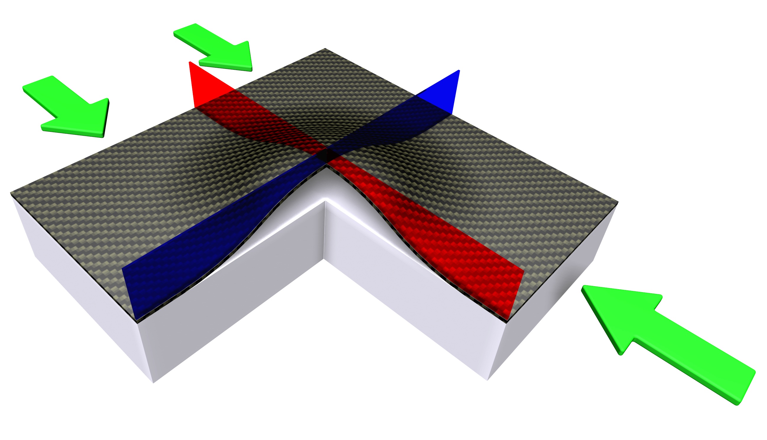
    Consider, for example, the schematic air inlet in the figure below and assume that it is designed to be fully open at low air speeds. Considering the tradeoff between cooling performance and drag described above, at a critical air speed we would like the air inlet to automatically snap-shut for drag reduction. Furthermore, once the air-speed increases, the air inlet should open-up again to facilitate cooling. Ideally, this mechanism is to be designed autonomously without recourse to additional sensors or actuators. In fact, the fluid flow over the inlet creates a pressure field which can be used to actuate the adaptive air inlet, and the amount of compression of the inlet, i.e. the post-buckled state, plays the role of an integral sensing and control system.

    Reproduced from Arena et al. (2017) Adaptive compliant structures for flow regulation. Proc.R.Soc.A 473: 20170334

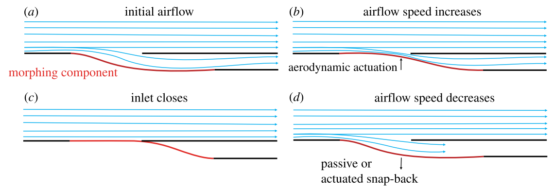
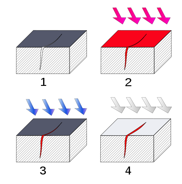
    An increase of fluid velocity into the inlet generates an area of low static pressure over the adaptive component. This pressure field is equivalent to a transverse load described above and causes the adaptive component to be sucked upwards. At a critical velocity, the low static pressure field exceeds the tipping point and the inlet snaps shut. If the device is designed to be bistable, then an additional actuation device is required to open the inlet up again. However, if the inlet is a monostable snapping device, then it will automatically open again once the airspeed is reduced and falls beneath a certain threshold. In this manner, a non-linear snapping air inlet can be used to automatically open and close a cooling duct purely by interacting with the fluid around it.

    In our lab we have built and successfully tested such an adaptive air inlet in a wind tunnel. The two options of bistable and monostable snapping behaviour are clearly visible in the video below. Our current research is looking into the question of whether this behaviour can be extended from bistability to multi-stability. This would allow us to introduce an intermediate stage between the fully open and closed states for reduced air flow into the duct.

    The question of control

    The shape-adaptive air inlet is an example of a passive morphing device. Passive control refers to the ability of a system to react and adapt to external stimuli without having additional sensory, information processing or actuating devices. For example, no pressure sensors were attached to the air inlet to provide a signal to an external actuator to close the duct. Instead, the sensing, actuating and control functions were entirely embedded within the non-linear mechanics of the air inlet. The pressure field provided the actuation, the tipping point acted as an on/off switch, and the inherent stability of the second configuration acted as control. Such passive control systems are attractive from a minimal design perspective, and nature has found uses for passive control in the ruffling of birds’ feathers and adaptive shark scales for boundary layer control.

    However, most shape-adaptive systems in nature are of the active type, where sensors (nerves) provide information to a central information processing unit (brain), which then provides an action signal to actuators (muscles). The beauty of biological organisms, may they be birds or even “smart” plants like the Venus flytrap, is that the entire control system of sensing, information processing and actuating is very efficiently contained within the organism. For example, the modern control systems of hydraulic lines and actuators that drive slats, flaps and control surfaces on an aircraft seem clumsy compared to the integral and lightweight solutions that evolution has crafted.

    Dionaea muscipula closing trap animation

    Of course, nature has undergone 4 billion years of evolution to arrive at these solutions, and so it is no wonder that our systems are comparatively ad hoc. But what seems crucial is that the three functions of sensing, information processing and actuation need to be scaled down, distributed more evenly and integrated tightly within the surrounding structure. Consider the musculoskeletal system of your arms, which can be understood as a tightly layered system. You have bones to provide structure, muscles layered on top for actuation, nerves running through muscles as lines of communication, and a further layer of skin to contain everything and provide sensory means to probe your surroundings (touch and heat).

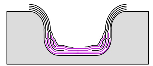
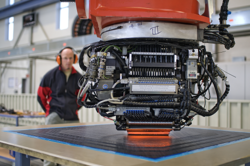
    Focusing on this concept of a layered structure, only in the last 1-2 decades have we gained the manufacturing expertise to produce such structures and materials with fidelity. Classic manufacturing techniques are subtractive in nature. Take a big billet of metal and cut everything away which is not your desired object. Contrast this to the modern additive manufacturing techniques of 3-D printing and laminated composite materials. Here, you create an object by layering material bit by bit, creating the whole unit from the bottom up. In the case of 3-D printing, a nozzle ejects material in pre-defined paths, whereas advanced composite laminates are manufactured by stacking layers of fibre-reinforced plastic on top of each other. Both these manufacturing techniques have the unique possibility of combining different material systems on the go, and even inserting additional components throughout the manufacturing process.

    For example, consider an analogue to your arm renditioned as multiple material layers. Take a couple layers of carbon fibre composite to provide structure, layer on top of that a layer of magnetostrictive or piezo-electric material as a muscle and a layer of modern thin-film integrated circuitry. Hold everything together by a soft, impact resistant layer studded with sensors, and voilá, there goes your cyborg arm. Of course, this is a dramatic over-simplification of a potential solution, and to date, entirely science fiction. But the utility of this thought experiment is to plant a flag somewhere ambitious, which can then serve as a motivating goal. We might not arrive at this precise reality in the future, but the technology that will be developed just by embarking on this journey will certainly be novel and exciting.

    Conclusion

    So here you have it: a vision for the future of shape-adaptive aircraft featuring smart and multi-functional materials/structures. Advances in material science, manufacturing technology and compliant integrated circuitry now allow us to embed intelligence into engineering structures. This means structures will no longer just resist loads but have other integrated functions like sensing, information processing and actuation embedded within them. Furthermore, appreciable shape changes imply a degree of non-linearity and the shift from avoiding non-linearity to exploiting it for novel functionality opens up an entirely new frontier for innovation.

    Acknowledgements

    As with most modern research, there is a group of engineers working on these ideas, and I am just one member of this group at the Bristol Composites Institute. The people involved in this project are Alberto Pirrera, Paul Weaver, Gaetano Arena, Raf Theunissen and Alex Brinkmeyer. The work on the adaptive air inlet was funded by the Engineering and Physical Sciences Research Council (EPSRC).

    Further Reading

  • Aeroelasticity, composites and the Grumman X-29

    Aeroelasticity is the study of the interactions between dynamic, inertial and aerodynamic forces that arise when a body is immersed in airflow. The unique challenge of aeroelasticity is to analyse how vibrations, static deflections and lift and drag forces combine, and to make sure that any interaction of these three forces does not lead to inferior aircraft performance or even failure.

    The triangle in the figure below is known as Collar’s triangle and each vertex shows one of the forces mentioned above. When all three forces interact simultaneously we are in the realm of aeroelasticity and common failure modes include wing flutter and buffeting. When inertial and elastic forces combine in the absence of aerodynamic forces we are in the classical domain of structural dynamics and essentially dealing with any sort of mechanical vibration that you would experience on any piece of moving machinery.  The interaction of inertial forces and aerodynamic forces gives rise to aerodynamic stability problems. How does an aircraft react to small disturbances – do the oscillations dampen out or do they get worse over time? Finally, the interaction of aerodynamic forces and elastic forces can give rise to a phenomenon known as divergence, which is an effect where twisting of the wing becomes theoretically infinite and can cause wings to twist off.

    The Collar Triangle defining aeroelasticity as “the study of the mutual interaction that takes place within the triangle of the inertial, elastic, and aerodynamic forces acting on structural members exposed to an airstream, and the influence of this study on design.”

    The two most dramatic aeroelastic effects are flutter and divergence. Flutter is a dynamic instability, often of the wing, caused by positive feedback between the wing’s deflection and the aerodynamic lift and drag forces. The flutter speed is the airspeed at which the wing, or any other part of the structure, starts to undergo simple harmonic motion – much like the simple to and fro motion of a simple pendulum – and this vibration occurs with zero net damping. Zero net damping means that there is no dissipation of energy (think of a pendulum swinging for eternity) and so any further decrease in net damping  will result in self-oscillation – the structure is basically forcing itself to vibrate more and more, which at some point, will naturally lead to failure.

    As we all know, the lift force acting on a wing will tend to bend it upwards, but what is less well-known is that this lift force can also cause the wing to twist. This is because the centre of pressure, the point where the total sum of the lift pressure field is assumed to act on an airfoil, is not necessarily coincident with the shear centre, the point through which a bending load needs to be applied to get pure bending without any twisting. Imagine holding a ruler in one hand and pushing up on it with your other hand. If you apply the load along the central axis of the ruler, the ruler will only bend, but if you apply the load at one of the two sides you can see the ruler bend and twist ever so slightly. Most of the time, the shear centre of an airfoil is not coincident with the centre of pressure, and so a lift force produces both bending and twisting. A critical phenomenon called divergence can occur when this twisting of a wing increases the angle of attack, which consequently increases the lift force further or creates further mismatch between shear centre and centre of pressure, so that a feedback loop ensues until the wing diverges or essentially shears off. In fact, one of the Wright Brothers’ main rivals in the race to being the first at heavier-than-air flight was Samuel Langley, whose prototype plane crashed into the Potomac river in Washington D.C., and this is now believed to have occurred as a results of torsional divergence. Furthermore, torsional divergence was a large problem with many WWI fighter planes and required a lot of additional stiffening of the wings.

    Divergence of wings in action

    Forward-swept wings

    One of the domains where divergence is particularly pernicious is in forward-swept wings. Simply put, wing sweep delays the onset of shock waves over the wings and therefore reduces the associated rise in aerodynamic drag caused by boundary layer separation. In slightly more detail, as air flows over a curved object, such as an aircraft wing, it accelerates due to centripetal forces and this means that an aircraft travelling slightly slower than Mach 1.0 (the speed of sound) can develop pockets of supersonic flow over areas with high local curvature, typically the wings or the canopy. For thermodynamic reasons, supersonic flows terminate in a shock wave which results in a sudden increase in the density of the air. This effect disturbs the smooth flow over the wing and creates vortices behind the aircraft, which means it is a form of parasitic drag. Sweeping the wing reduces the curvature of the body as seen from the airflow by the cosine of the angle of sweep. For example, a 45 degree sweep reduces the effective curvature by around 70% ([latex]\cos 45^\circ = 0.71[/latex]) compared to the straight-wing case. As a result, this increases the airspeed at which supersonic pockets start to form by about 30%, such that the aircraft can reach speeds much closer to Mach 1 before shocks occur.

    Another way to think about the effect of sweep is to imagine the airflow over the wing as shown in the figure below. The effect of sweeping is such as to break the airflow into a component normal to the wing chord (“normal component”), and one along the span of the wing (“spanwise component”). The maximum curvature of the wing occurs along the wing chord, and the normal velocity component for the swept wing ([latex] V \cos \psi [/latex]) is always less than the normal component for a straight wing ([latex]V[/latex]).

    The figure above highlights another critical aspect of swept wings: the spanwise component. On a backward-swept wing the spanwise flow is outwards and towards the tip, while on a forward-swept wing it is inwards towards the root (see the figure below). Firstly, with the air flowing inwards towards the fuselage, wingtip vortices and the accompanying drag are reduced. Wingtip vortices form when the higher pressure air underneath the wing is sucked up onto the lower pressure top surface of the wing, thereby reducing the effective lift-generating surface of the wing. On most modern backward-swept airliners, winglets and sharklets prevent this phenomenon from occurring. Forward-swept wings similarly minimise this effect by re-routing some of the flow towards the wing root, and therefore allow for a smaller wing at the same lift performance. The second advantage of forward-swept wings is that shockwaves tend to develop first at the root of the wing, rather than towards the tips, and this helps to reduce tip stall. Aerodynamic control surfaces such as ailerons are typically located near the tips of the wings, because the further outboard, the greater their effect on controlling the rolling action of the plane. Tip stall essentially renders these ailerons useless, and therefore jeopardises the pilot’s control over the aircraft. As a result, the dangerous tip stall condition of a backward-swept design becomes a safer and more controllable root stall on a forward-swept design, providing better manoeuvrability at high angles of attack.

    Airflow forward and backward swept aircraft

    For all their merits, forward-swept wings suffer from one detrimental flaw – divergence. In a forward-swept wing configuration, the aerodynamic lift causes a twisting force that rotates the leading edge upward, causing a higher angle of attack, which in turn increases lift, and twists the wing further. With conventional metallic construction, additional torsional stiffening is typically required which adds weight, and is therefore sub-optimal in terms of aircraft performance.

    Enter the Grumman X-29

    The Grumman X-29 was an experimental aircraft developed by Grumman in the 1980’s, and flown by NASA and the US Air Force. The X-29 tested a forward-swept wing, canard control surfaces, and computerised fly-by-wire control to counter balance the various aerodynamic instabilities created by its airframe. From my perspective, the most important innovation, however, was the novel use of composite materials to control the aeroelastic divergence of forward-swept wings. At the time, composite materials were popular in the high-performance aircraft community as a means of creating stiff and strong structures at very low weight. In fact, composites were mainly used to save weight. However, the X-29 showcased a second advantage of this new material over classic metallic structures – multi-functionality.

    X-29 at High Angle of Attack with Smoke Generators

    Metals are isotropic materials, meaning that their stiffness is the same in all directions. The relationship between stress and strain along one direction of an aluminium panel is the same as in any other direction. Because composite materials are a union of stiff fibres held together by a resin matrix, we can manufacture panels that are stiffer in one direction than in another. This is because the composite material will be very stiff along the fibre direction but relatively compliant perpendicular to the fibre direction. In most fibre-reinforced composite materials, such as fibreglass and carbon fibre, this variation in stiffness is restricted to the plane of a single sheet of material known as an orthotropic lamina.

    Consider one such layer of a continuous fibre-reinforced composite in the figure above. The material axes 1-2 denote the stiffer fibre in the 1-direction and the weaker resin in the 2-direction. If we align the fibres with the global x-axis and apply a load in the x-direction, the layer will stretch along the fibres and compress in the resin direction (or vice versa). However, if the fibres are aligned at an angle to the x-direction (of say 45°), and a load is applied in the x-direction, then the layer will not only stretch in the x-direction and compress in the y-direction but also shear. This is because the layer will stretch less in the fibre direction than in the resin direction. This effect can be precluded if the number of +45° layers is balanced by an equal amount of -45° layers stacked on top of each other to form a laminate, e.g. a [45,-45,-45,45] laminate. However, this [45,-45,-45,45] laminate will exhibit bend-twist coupling because the 45° layers are placed further away from the mid plane than the the -45° layers. The bending stiffness of a layer is a factor of the layer-thickness cubed plus the distance from the axis of bending (here the mid-plane) squared. Thus, even if the +45° and -45° layers have the same thickness, the outer 45° layers contribute more to the bending stiffness of the [45,-45,-45,45] laminate than the -45° layers do. Therefore, stretching-shearing coupling is eliminated in a [45,-45,-45,45] laminate as the number of +45° and -45° layers is the same, but bend-twist coupling will occur because the +45° layers are further from the mid-plane than the -45° layers.

    Let’s now apply this effect at a wing level, i.e. a [latex][+\theta,-\theta][/latex] layup is used for the top wing surface and a [latex][-\theta,+\theta][/latex] layup for the bottom wing surface. At the global wing level, the layup  is balanced because we have an equal number of [latex]+\theta[/latex] and [latex]-\theta[/latex] layers, but the [latex]+\theta[/latex] layers are further away from the wing mid-plane than the [latex]-\theta[/latex] layers. This means that the bending stiffness is dominated by the [latex]+\theta[/latex] layers, and the wing will twist when it bends.

    In the Grumman X-29, this bend-twist coupling was successfully exploited to prevent divergence in the forward-swept wings. As aerodynamic lift forces the wing tips to bend upward, the forward-swept wing wants to twist to higher angles of attack, but the inherent bend-twist coupling of the composite laminates forces the wing to twist in the opposite direction and thereby counters an increase in the angle of attack – divergence is avoided!

    Bend-twist coupling in Grumman X-29 wings. Both top and bottom wing skin may have the same number of +theta and -theta fibre angles, but if the +theta angles are further from the wing mid-plane then they will dominate the bending behaviour and cause the leading edge to twist down as the wing bends up.

    The Grumman X-29 is an excellent example of an efficient, autonomous and passively activated control system. Rather than adding more material to the wing to make it stiffer (but also heavier) an alternative solution is to use the bend-twist coupling capability of composite laminates. This capability is an example of elastic tailoring, and remains one of the most under-exploited advantages of composite materials. As the big aircraft manufacturers overcome the initial hurdles of using composites on a large scale with the 787 Dreamliner and A350-XWB, expect more and more of these multi-functional capabilities of composites to find their way onto aircraft components.

  • Rocket Science 101: Lightweight rocket shells

    This is the fourth and final part of a series of posts on rocket science. Part I covered the history of rocketry, Part II dealt with the operating principles of rockets and Part III looked at the components that go into the propulsive system.

    One of the most important drivers in rocket design is the mass ratio, i.e. the ratio of fuel mass to dry mass of the rocket. The greater the mass ratio the greater the change in velocity (delta-v) the rocket can achieve. You can think of delta-v as the pseudo-currency of rocket science. Manoeuvres into orbit, to the moon or any other point in space are measured by their respective delta-v’s and this in turn defines the required mass ratio of the rocket.

    For example, at an altitude of 200 km an object needs to travel at 7.8 km/s to inject into low earth orbit (LEO). Accounting for frictional losses and gravity, the actual requirement rocket scientists need to design for when starting from rest on a launch pad  is just shy of delta-v=10 km/s. Using Tsiolovsky’s rocket equation and assuming a representative average exhaust velocity of 3500 m/s, this translates into a mass ratio of 17.4:

    Δv=|ve|lnM0MflnM0Mf=100003500=2.857\Delta v = \left|v_e\right| \ln \frac{M_0}{M_f} \Rightarrow \ln \frac{M_0}{M_f} = \frac{10000}{3500}=2.857
    M0Mf=e2.86=17.4\therefore \frac{M_0}{M_f} = e^{2.86} = \underline{17.4}

    A mass ratio of 17.4 means that the rocket needs to be 117.41=94.31-17.4^{-1} = 94.3% fuel!

    This simple example explains why the mass ratio is a key indicator of a rocket’s structural efficiency. The higher the mass ratio the greater the ratio of delta-v producing propellant to non-delta-v producing structural mass. The simple example also explains why staging is such an effective strategy. Once, a certain amount of fuel within the tanks has been used up, it is beneficial to shed the unnecessary structural mass that was previously used to contain the fuel but is no longer contributing to delta-v.

    At the same time we need to ask ourselves how to best minimise the mass of the rocket structure?

    So in this post we will turn to my favourite topic of all: Structural design. Let’s dig in…


    The role of the rocket structure is to provide some form of load-bearing frame while simultaneously serving as an aerodynamic profile and container for propellant and payload. In order to maximise the mass ratio, the rocket designer wants to minimise the structural mass that is required to safely contain the propellant. There are essentially two ways to achieve this:

    • Using lightweight materials.
    • And/or optimising the geometric design of the structure.

    When referring to “lightweight materials” what we mean is that the material has high values of specific stiffness, specific strength and/or specific toughness. In this case “specific” means that the classical engineering properties of elastic modulus (stiffness), yield or ultimate strength, and fracture toughness are weighted by the density of the material. For example, if a design of given dimensions (fixed volume) requires a certain stiffness and strength, and we can achieve these specifications with a material of superior specific properties, then the mass of the structure will be reduced compared to some other material. In the rocket industry the typical materials are aerospace-grade titanium and aluminium alloys as their specific properties are much more favourable than those of other metal alloys such as steel.

    However, over the last 30 years there has been a drive towards increasing the proportion of advanced fibre-reinforced plastics in rocket structures. One of the issues with composites is that the polymer matrices that bind the fibres together become rather brittle (think of shattering glass) under the cryogenic temperatures of outer space or when in contact with liquid propellants. The second issue with traditional composites is that they are more flammable; obviously not a good thing when sitting right next to liquid hydrogen and oxygen. Third, it is harder to seal composite rocket tanks and especially bolted joints are prone to leaking. Finally, the high-performance characteristics that are needed for space applications require the use of massive high-pressure, high-temperature ovens (autoclaves) and tight-tolerance moulds which significantly drive up manufacturing costs. For these reasons the use composites is mostly restricted to payload fairings. NASA is currently working hard on their out-of-autoclave technology and automated fibre placement technology, while Rocket Lab already uses carbon-composite rockets.

    The load-bearing structure in a rocket is very similar to the fuselage of an airplane and is based on the same design philosophy: semi-monocoque construction. In contrast to early aircraft that used frames of discrete members braced by wires to sustain flight loads and flexible membranes as lift surfaces, the major advantage of semi-monocoque construction is that the functions of aerodynamic profile and load-carrying structure are combined. Hence, the visible cylindrical barrel of a rocket serves to contain the internal fuel as a pressure vessel, sustains the imposed flights loads and also defines the aerodynamic shape of the rocket. Because the external skin is a working part of the structure, this type of construction is known as stressed skin or monocoque. The even distribution of material in a monocoque means that the entire structure is at a more uniform and lower stress state with fewer local stress concentrations that can be hot spots for crack initiation.

    Second, curved shell structures, as in a cylindrical rocket barrel, are one of the most efficient forms of construction found in nature, e.g. eggs, sea-shells, nut-shells etc. In thin-walled curved structures the external loads are reacted internally by a combination of membrane stresses (uniform stretching or compression through the thickness) and bending stresses (linear variation of stresses through the thickness with tension on one side, compression on the other side, zero stress somewhere in the interior of the thickness known as the neutral axis). As a rule of thumb, membrane stresses are more efficient than bending stresses, as all of the material through the thickness is contributing to reacting the external load (no neutral axis) and the stress state is uniform (no stress concentrations).

    In general, flat structures such as your typical credit card, will resist tensile and compressive external loads via uniform membrane stresses, and bending via linearly varying stresses through the thickness. The efficiency of curved shells stems from the fact that membrane stresses are induced to react both uniform stretching/compressive forces and bending moments. The presence of a membrane component reduces the peak stress that occurs through the thickness of the shell, and ultimately means that a thinner wall thickness and associated lower component mass will safely resist the externally applied loads. This is important as the bending stiffness of thin-walled structures is typically at least an order of magnitude smaller than the stretching/compressive stiffness (e.g. you can easily bend your credit card, but try stretching it).

    Alas, as so often in life, there is a compromise. Optimising a structure for one mode of deformation typically makes it more fragile in another. This means that if the structure fails in the deformation mode that it has been optimised for, the ensuing collapse is most-likely sudden and catastrophic.

    As described above, reducing the wall-thickness in a monocoque construction greatly helps to reduce the mass of the structure. However, the bending stiffness scales with the cube of the thickness, whereas the membrane stiffness only scales linearly. Hence, in a thin-walled structure we ideally want all deformation to be in a membrane state (uniform squashing or stretching), and curved shell structures help to guarantee this. However, due to the large mismatch between membrane stiffness and bending stiffness in a thin-walled structure, the structure may at some point energetically prefer to bend and will transition to a bending state.

    This phenomenon is known as buckling and is the bane of thin-walled construction.

    One of the principles of physics is that the deformation of a structure is governed by the proclivity to minimise the strain energy. Hence, a structure can at some point bifurcate into a different deformation shape if this represents a lower energy state. As a little experiment, form a U-shape with your hand, thumb on one side and four fingers on the other. Hold a credit card between your thumb and the four fingers and start to compress it. Initially, the structure reacts this load by compressing internally (membrane deformation) in a flat state, but very soon the credit card will snap one way to form a U-shape (bending deformation).

    The reason this works is because compressing the credit card reduces the distance between two edges held by the thumb and four fingers. The credit card can satisfy these new externally imposed constraints either by compressing uniformly, i.e. squashing up, or by maintaining its original length and bending into an arc. At some critical point of compression the bending state is energetically more favourable than the squashed state and the credit card bifurcates. Note that this explanation should also convince you that this form of behaviour is not possible under tension as the bifurcation to a bending state will not return the credit card to its original length.

    The advantage of curved monocoques is that their buckling loads are much greater than those flat plates. For example, you can safely stand on a soda can even though it is made out of relatively cheap aluminium. However, once the soda can does buckle all hell breaks loose and the whole thing collapses in one big heap. What is more, curved structures are very susceptible to initial imperfections which drastically reduce the load at which buckling occurs. Flick the side of a soda can to initiate a little dent and stand back on the can to feel the difference.

    Imperfection sensitivity of a cylinder. The plot shows the drastic reduction in load that the cylinder can sustain with increasing deformation once the buckling point has been passed.
    Imperfection sensitivity of a cylinder. The plot shows the drastic reduction in load (vertical axis) that the perfect cylinder can sustain with increasing deformation (horizontal axis) once the buckling point has been passed. This means that an imperfect (real) shell will never reach the maximum load but diverge to the lower load level straight away.

    This problem is exacerbated by the fact that the shape of the tiny initial imperfections, typically of the order of the thickness of the shell, can lead to vastly different failure modes. Thus, the behaviour of the shell is emergent of the initial conditions. In this domain of complexity it is very difficult to make precise repeatable predictions of how the structure will behave. For this reason, curved shells are often called the “prima-donna” of structures and we need to be very careful in how we go about designing them.

    A rocket is naturally exposed to compressive forces as a result of gravity and inertia while accelerating. In order to increase the critical buckling loads of the cylindrical rocket shell, the skin is stiffened by internal stiffeners. This type of construction is known as semi-monocoque to describe the discrete discontinuities of the internal stiffeners. A rocket cylinder typically has internal stringers running top to bottom and internal hoops running around the circumference of the cylindrical skin.

    Space Shuttle internal structure of propellant tank. Note the circumferential hoops and longitudinal stringers that help, among other things, to increase the buckling load.

    The purpose of these stringers and hoops is twofold:

    • First, they help to resist compressive loading and therefore remove some of the onus on the thin skin.
    • Second, they break the thin skin into smaller sections which are much harder to buckle. To convince yourself, find an old out-of-date credit card, cut it in half and repeat the previously described experiment.

    The cylindrical rocket shell has a second advantage in that it acts as a pressure vessel to contain the pressurised propellants. The internal pressure of the propellants increases the circumference of the rocket shell, and like blowing up a balloon, imparts tensile stretching deformations into the skin which preempt the compressive gravitational and inertial loads. In fact, this pressure stabilisation effect is so helpful that some old rockets that you see on display in museums, most notoriously the Atlas 2E rocket, need to be pressurised artificially by external air pumps at all times to prevent them from collapsing under their own weight. If you look at the diagram below you can see little diamond-shaped dimples spread all over the skin. These are buckling waveforms.

    Atlas 2E Ballistic Missile (via Wikimedia Commons)
    Atlas 2E Ballistic Missile with buckling “diamonds” along the entire length of the external rocket skin (via Wikimedia Commons)

    NASA Langley Research Center has been, and continues to be, a leader in studying the complex failure behaviour of rocket shells. To find out more, check out the video by some of the researchers that I have worked with who are developing new methods of designing the next generation of composite rocket shells.

  • Variable Stiffness Composites

    In previous posts I have discussed the unique characteristics and manufacturing processes of a certain type of composite material, namely continuous fibre-reinforced plastics (FRPs). Just like many other composite materials, FRPs combine two or more materials whose combined properties are superior (in a practical engineering sense) to the properties of the constituent materials on their own. What distinguishes FRPs from other composites such as short-fibre composites, nanocomposites or discrete particle composites are the highly aligned, long bundles of fibres typically glass or carbon that are arranged in a specific direction within some resin system.

    The biggest advantage of FRPs compared to metals is not necessarily their greater specific strength and stiffness (i.e. strength/density and stiffness/density) but the increased design freedom to tailor the structural behaviour. Metals and ceramics, being isotropic materials, behave in an intuitive way since the majority of the coupling terms in the stiffness tensor vanish. If you a imagine a three-dimensional cube and pull two opposing faces apart then the other two pairs of opposing faces will move towards each other. This phenomenon of coupling between tension and compression is known as the Poisson’s effect and aptly captured by the Poisson’s ratio.

    The Poisson's effect in action
    The Poisson’s effect in action

    In bending, a similar phenomenon occurs known as anti-clastic curvature. If you have ever tried bending a thin, beam-like structure made out of a soft material e.g. a rubber eraser, you might have noticed that the beam wants to develop opposite curvature in the transverse direction to the main bending axis. The structure morphs into some form of saddle shape as shown in the figure. The phenomenon occurs because the bending moment applied by the person in the picture causes tension in the top surface and compression in the bottom surface in the direction of applied bending. From the Poisson’s effect we know that this induces compression in the top surface and tension in the bottom surface in the transverse direction. By analogy, this is exactly the reverse of the bending moment applied by the hands and so the panel bends in the opposite sense in the transverse direction.

    Anticlastic curvature in action (1)
    Anticlastic curvature in action (1)

    For isotropic materials the fundamental linear constitutive equations between stress and strain eliminate a lot of the possible coupling behaviour. There is no coupling between applied bending moments and twisting. No coupling between stretching/compressing and bending/twisting. And also no coupling between stretching/compressing and shearing. FRPs, being orthotropic materials, i.e. having two orthogonal axes of different material properties, can display all of these effects. Consider a single layer of a continuous fibre-reinforced composite in the figure below. The material axes 1-2 denote the stiffer fibre in the 1-direction and the weaker resin in the 2-direction. If we align the fibres with the global x-axis and apply a load in the x-direction, the layer will stretch/compress along the fibres and compress/stretch in the resin direction in the same way as described previously for isotropic materials. However, if the fibres are aligned at an angle to the x-direction say 45°, and a load is applied in the x-direction then the layer will not only stretch/compress in the x-direction and compress/stretch in the y-direction but also shear. This is because the layer will stretch/compress less in the fibre direction than in the resin direction. This effect can be precluded if the number of +45° layers is balanced by an equal amount of -45° layers stacked on top of each other to form a laminate, e.g. a [45,-45,-45,45] laminate. However, this [45,-45,-45,45] laminate will exhibit bend-twist coupling because the 45° layers are placed further away from the mid plane than the the -45° layers. The bending stiffness of a layer is a factor of the layer thickness cubed and the distance from the axis of bending (here the mid plane) squared. Thus, the outer 45° layers contribute more to the bending stiffness of the laminate than the -45° layers such that the coupling effects do not cancel.

    A single fibre reinforced plastic layer with material and global coordinate systems
    A single fibre reinforced plastic layer with material and global coordinate systems

    Using metals, structural designers were constrained to tailoring the shape of a structure to optimise its performance i.e. thickness, length and width, and overall profile/shape. FRPs however add an extra dimension for optimisation by allowing designers to tailor the properties through the thickness and thereby achieve all kinds of interesting effects. For example, forward-swept wings on aircraft have and still are a nightmare due to aeroelastic instabilities like flutter and divergence. Basically, sweeping a wing forward is a neat idea because the airflow over swept wings flows spanwise towards the end furthest to the rear of the plane. Therefore, the tip-stall condition characteristic of backward-swept wings is moved towards the fuselage where it can be controlled more effectively.  The drawback is that as the lift force bends the wingtip upwards the angle of attack increases, further increasing the lift and thereby causing more bending, and so on until the wings snap off or fail. Rather than adding more material to the wing to make it stiffer (but also heavier) an alternative solution is to use the bend-twist coupling capability of composite laminates. This was successfully achieved in the iconic Grumman X-29. As the bending loads force the wing tips to bend upward and twist the wing to higher angles of attack, the inherent bend-twist coupling of the composite laminate used forces the wing to twist in the opposite direction and thereby counters an increase in the angle of attack. This is an excellent example of an efficient, autonomous and passively activated control system to prevent divergence failure.

    Grumman X-29 with forward-swept wings
    Grumman X-29 with forward-swept wings

    In this manner, straight fibre composites allow structural engineers to change the stiffness and strength properties through the thickness in order to tailor the structural behaviour. The concept of variable stiffness composites adds a further dimension to the capability for tailoring. Currently this is achieved by spatially varying the point wise fiber orientations by actively steering individual fibre tows using automatic fibre placement machines. One early application that was considered by researchers was improving the stress concentrations around holes by steering fibres around them.

    Automated Fibre Placement machine (2)
    Automated Fibre Placement machine (2)

    This concept can be generalised by aligning fibres with the direction of local primary load paths which could vary across different parts of the structure. Tow steering creates the possibility for designing blended structures by facilitating smooth transitions between areas with different layup requirements. One promising application of variable stiffness composites is in buckling and postbuckling optimisation of flat and curved panels. As a panel is compressed uni-axially the capability of the panel to resist transverse bending loads reduces until a critical level is reached where the panel has lost all capability to sustain any bending loads. At this point known as the buckling load, the fundamental state of compression becomes unstable and the panel buckles outward in a single or multiple waves. It has been found that variable stiffness composites can double the buckling load of flat panels by favourably redistributing the load paths in the fundamental, pre-buckling compression state. Essentially, the middle of the panel where the buckling waves will occur is offloaded, and the edges of the panel are forced to take more load. Thus, the aim is to redirect loads to locally supported regions and remove load from regions remote from supported boundaries. This concept has also been extended to improving aircraft fuselage sections and blade-stiffened panels.

    A variable angle tow laminate
    A variable angle tow laminate (3)

    This new technology is viewed as a promising candidate for further reducing the mass of future aerospace structures. In fact recently NASA Langley Research Centre announced that they are investing heavily in this capability. The possibility of manufacturing integrated structures with smooth flow of material between components and minimal joints will not only revolutionise stress-based design, but also simplify manufacturing and facilitate entirely new aircraft designs that are currently unfeasible. In trees for example, there is a smooth transition of fibres from the trunk into the branches to strengthen the connecting joint. With the variable stiffness capabilities investigated by NASA we could apply this concept to simplify and even strengthen critical interfaces such as fuselage-wing connections.

    References

    (1) http://www.astm.org/HTTP/IMAGES/70104.gif

    (2) http://csmres.co.uk/cs.public.upd/article-images/Premium-nordenham.jpg

    (3) Kim et al. (2012). “Continuous Tow Shearing for Manufacturing Variable Angle Tow Composites”. Composites: Part A, 43, pp. 1347-1356


  • Defects and Non-Destructive Testing in Composites

    The treatment of defects in aircraft structural design has been an important aspect in aircraft structural design during the last 50 years. Various different catastrophic events have led to key insights that now shape the design philosophy for primary aircraft structures. One of these is the distinction between Safe-Life and Fail-Safe structures. Safe-Life components are designed to go through their service life without cracks and defects playing a major role in the stress state of the component. Thus, the required fatigue life to initiate a crack is kept below the anticipated service life. This design approach is mainly used for components for which there are no back-ups in place and where failure would lead to the loss of the aircraft. A typical example of a Safe-Life component is the landing gear and this remains one of the reasons why landing gears are made from high-strength steel for which engineers have a long history of structural data. The second “Fail-Safe” design philosophy assumes that any real manufacturing process will induce defects within the part that, even if microscopic, may vary between different batches and may grow during the service life. Thus the Fail-Safe components are structurally designed to withstand all imposed loads up to a certain certain level of defect, known as the “critical size”, which can usually be detected by eye and act as stress concentrators. In this manner critical components are continuously monitored at specific service intervals to make sure that no crack exceeds the critical defect size, and is subsequently replaced if this happens. Furthermore, crack propagation analyses are employed in order to ascertain how many flights/load cycles it will take to grow a crack to the critical size. Most of these insights stem from the experience engineers have gained during the last 50 years with metal aircraft and in fact there was quite a steep learning curve during the transition years from wood to metal aircraft.

    Today we are facing a similar transition from metal to mostly fibre reinforced plastics and other advanced materials whose failure mechanisms are often much more complex than that of metals. First, in metallic structures a crack typically initiates at an imperfection or stress concentration and then propagates under fatigue loading until final failure. The damage morphology in composites however is completely different: a large number of microscopic defects, such as micro-cracks that occur during post-cure shrinkage of the resin are present over a large volume of the material and these may develop into different failure mechanism over time. Second, most metals have a ductile failure mechanism such that overloading can visually be detected by the onset of plastic deformation. Therefore there is often a warning period between a structure being overloaded and failing catastrophically. Fibre reinforced plastics, especially carbon fibre composites on the hand fail by more brittle and therefore sudden mechanisms. Third, while a major driver of component design for metal structures is crack growth, which can be predicted quite accurately today using analytical methods or Finite Element codes, fibre reinforced plastics have a plethora of other failure mechanisms and manufacturing defects that are equally important. Some examples are fibre breakage, matrix cracks, matrix-fibre debonding, delaminations, voidage, misplacement of plies, lack of impregnation and fibre waviness. Interlaminar failures such as delaminations are especially important since they can occur very quickly when a laminate is loaded through the thickness, for example at stringer run-outs, in corner-radii of C-spars or simple impact events such as tool drop in the factory. Since there are typically no reinforcing fibres in the perpendicular direction the structural integrity is only guaranteed by the weak matrix. Due to this inherent weakness different plies may literally be pulled apart at their lamination interfaces. Techniques such as through thickness reinforced such as 3D braiding, Z-Pinning or nano-fibre reinforcement are currently being researched. Under compressive forces these delaminations may form blisters, so called delimitation buckling, which can easily propagate along the lamination interface leading to disintegration of the part.

    Fig. 1 Delamination Buckling in Composite Laminate

    Finally, different failure mechanisms actually interact making accurate predictions of the failure load including a defect extremely difficult. Furthermore, even experimental data for laboratory sized specimens cannot readily be used for real-sized components since the scaling up of structures has been found to greatly alter the dominant failure mechanism. Finally, failure sites in fibre reinforced plastics are often internal meaning that an engineer will not be able to detect them by simple visual investigation during service intervals. As a result, the increasing use of fibre reinforced plastic construction during the recent years and near future means more sophisticated evaluation techniques are required for guaranteeing safe design and operation of aircraft. Another key question is how these new types of defects can be taken into account reliably in structural design?

    Compared to metallic materials composites have a very unique characteristic in that the material and structure/part are created simultaneously. This means that the amount of imperfections in the part is greatly dependent on the manufacturing process. In composite materials the fail-safe design philosophy of degrading the material properties to that including a “critical defect size” is not only important to reduce the probability of failure as in metallic structures but also because a manufacturing process free from imperfections would be financially prohibitive. Thus, the degree of process and quality control depends greatly on the safety requirements of the industry. For example, the high-volume and competitive automobile sector needs to guarantee passenger safety while keeping manufacturing costs at a minimum. In the aerospace industry however the mass of components is absolutely critical and takes precedence over the manufacturing costs. As a result the automobile industry relies more on out-of-autoclave infusion processes that allow high production volumes such as Resin Transfer Moulding, while the aerospace industry currently relies on the high-temperature, high-pressure curing environments of the autoclave that allow the manufacture of high performance parts with low, controlled level of imperfections.

    Non-destructive testing (NDT) methods are often employed to detect defects inside or on the surface of a material. In general they are broken down into surface methods, bulk volume methods and global methods. These methods are typically used at the end of the manufacturing process as a quality control measure or during the life of the part to monitor and assess its fitness for continuing use. Surface methods include visual inspection techniques such as scanning the surface for obvious cracks, porosities, resin rich/starved regions or surface waviness. This is often coupled with endoscopes to examine remote or difficult to access locations. Furthermore a common technique is dye penetrant inspection where a dye is applied to external surfaces and illuminated with an ultraviolet light in order to highlight cracks on the surface that the dye has crept into. This technique was quite popular for aero engine components but is inherently quite time and labour intensive.

    1. Section of material with a surface-breaking crack that is not visible to the naked eye. 2. Penetrant is applied to the surface. 3. Excess penetrant is removed. 4. Developer is applied, rendering the crack visible. (1)
    1. Section of material with a surface-breaking crack that is not visible to the naked eye.
    2. Penetrant is applied to the surface.
    3. Excess penetrant is removed.
    4. Developer is applied, rendering the crack visible. (1)

    Bulk volume methods range from the simple tap test to ultrasonic screening to the most sophisticated X-ray and computer tomography techniques. The choice of the method depends greatly on the type of defect that is to be detected and criticality of cycle time and production costs. Simple surface defects, core crush in sandwich structures may easily be detected using visual techniques, while tap tests can be used very effectively to determine delaminations or large internal voids. In a tap test the component is tapped lightly with a hard object such as a coin or ring which emits a very dull sound if a delimitation lies beneath the testing point. On the other hand the exact location and size of a delimitation, possible contaminations, voids or micro-porosities can only be detected with ultra-sonic or C.T. techniques. In this respect ultra-sonic scanning has developed to be the most widely-used NDT technique in the aerospace industry due to its high detection fidelity, compactness and relative low-cost compared to C.T. techniques. In ultra-sonic scanning ultrasound is projected into a component and by measuring the strength and time delay of the echo it is possible to detect inclusions (air, solid objects etc.) that differ from the host composite material.

    Principle of ultrasonic testing. LEFT: A probe sends a sound wave into a test material. There are two indications, one from the initial pulse of the probe, and the second due to the back wall echo. RIGHT: A defect creates a third indication and simultaneously reduces the amplitude of the back wall indication.
    Fig. 3. Principle of ultrasonic testing. LEFT: A probe sends a sound wave into a test material. There are two indications, one from the initial pulse of the probe, and the second due to the back wall echo. RIGHT: A defect creates a third indication and simultaneously reduces the amplitude of the back wall indication. (2)

    One of the drawbacks of ultrasonic scanning is that some sort of coupling agent (typically water or a gel) is required between the probe and surface of the part to guarantee a high-quality reading. Furthermore, the scanning of large areas can be very time intensive even with the use of multi-probe ultrasonic arrays that can be rolled across a surface or controlled by a robotic arm, such that this technique is typically restricted to critical or highly-stressed components. Finally, CT techniques are currently only widely used in academia where they can give very useful insight into the exact 3D morphology of a cured part and show how and where cracks are initiated and when they propagate. Some pieces of equipment like Synchrotron radiation computed tomography at the University of Southampton can produce extremely detailed 3D plots and videos of parts under load that are very useful to help researchers understand what drives failure in composite materials.

    Fig. X. 3D Synchrotron Image (2)
    Fig. 4. 3D Synchrotron Image (3)

    Finally, in recent years global methods such as structural health monitoring have been a hot research topic. In structural health monitoring sensors such as strain gauges or fibre-bragg grating systems are embedded within the structure and provide real time data on the stress state. In this manner the health of the structure can be monitored in real time and service intervals and replacement parts be installed at the required times. However, these systems can probably not be embedded throughout an entire aircraft and require an incredible amount of storage to cope with the continual data stream.

    Understanding the detrimental effects of imperfections and the damage mechanisms is essential in order to take full advantage of the benefits that high performance composites have to offer. In this respect non-destructive testing is a very valuable tool for investigating and mapping the internal condition of a component. One of the challenges facing the aerospace and automobile industries in the future is deciding what detail of non-destructive testing is required to guarantee the structural integrity of the products to a high degree of probability during the entirety of its service life and balancing this against the cost that the specific techniques incur.

    Image Credit and Sources

    (1) Wikipedia, http://en.wikipedia.org/wiki/File:Ressuage_principe_2.svg

    (2) Wikipedia, http://en.wikipedia.org/wiki/File:UT_principe.svg

    (3) Institute of Materials Science and Technology – Vienna University of Technology, http://mmc-assess.tuwien.ac.at/mmc/?mid_detail=99

  • Composite Materials and Renewables: Wind Energy

    In the aerospace industry the benefits of exploiting the excellent specific strength and stiffness properties of composites in terms of lightweight structural design are immediately apparent. Other advantages of fibre reinforced plastics, such as the relative ease to manufacture complex shapes, and their excellent fatigue and corrosion resistance, have made FRP composites increasingly attractive in the renewable energy sector. Considering the predicted growth of production in wind turbines, accounting for nearly 60% of the entire advanced composites market by 2020 [1], a wide variety of scientific material has been published in recent years regarding the optimisation of advanced composites usage in wind turbines. Furthermore, considerable “blue-sky” research is being conducted that aims to take advantage of the multifunctional capabilities of advanced composites in order to extend their integration in less obvious applications such as tidal turbines and solar panels. The objective of this post is to give a general overview of the novel research conducted to facilitate these new technologies, while giving a more detailed insight into the challenges that engineers face in designing the new generation of 100m wind turbine blades.

    Overview

    In the last 25-30 years the use of wind turbines for electricity generation has grown from a grass-root “green” initiative to a financially sustainable

    Fig. 1. Correlation of increasing rotor diameter and power rating throughout the last 30 years [3].
    Fig. 1. Correlation of increasing rotor diameter and power rating throughout the last 30 years [3].

    primary energy resource [2]. The increasing maturity of the industry can be traced from the small 100-150 kW turbines constructed throughout the 1980s to the large 2-5 MW projects installed both on- and offshore today. This growth can largely be attributed to innovations in the integration of lightweight fibre-reinforced plastics (FRPs), which have facilitated increasingly larger blade lengths as shown in Figure 1. Fibre-reinforced plastics represent a prime material choice for wind turbine blades in terms of structural efficiency since the high specific stiffness limits tip deflections, reduces gravity-induced loading and decreases rotor inertia. Furthermore, the excellent fatigue resistance of FRPs helps to minimise material degradation and maintenance costs over the 20-year design lifespan [4]. A few of the currently largest wind turbines including their blade materials are summarised in Table 1.

    Table 1: Summary of various Megawatt wind turbines with defining characteristics and blade material choices [5] – [9].

     Company

    Model

     Blade

     Length (m)

      Rotor ø

    (m)

    Power

    (MW)

    Blade Materials

      Vestas

     V120-3MW

      54.65

     NA

    3

    glassfiber/carbon spars with glassfiber

    airfoil shells

      Enercon

     E-126

     NA

     127

    7.5

    glassfiber/epoxy with steel mesh for

    lightning strike

      Siemens

     SWT-3.6-120

     58.5

     120

    3.6

    glassfiber/epoxy composite

      Gamesa

     G136-4.5 MW

     66.5

     136

    4.5

    Organic matrix composite reinforced

    with fiber glass or carbon fiber

      Suzlon

     S88-2.1MW

     NA

     88

    2.1

    glassfiber/epoxy composite

    However, as governmental subsidies run out the long-term growth of wind technology depends on increasing the energy capture efficiency and therefore turbine sizes. This will require further innovation in lightweight structural design by means of multi-functional and stronger materials, as well as cost-effective manufacturing and installation. A current base model wind turbine section is shown in Figure 2.

    Fig. 2. A base model wind turbine section with load-carrying box and attached shells [10].
    Fig. 2. A base model wind turbine section with load-carrying box and attached shells [10].

    The Challenge of Designing a 100m Blade

    Glassfibre reinforced plastics (GFRPs) were selected in the early wind turbine days because of good material availability and well-documented processing technology. The weight of a turbine blade can statistically been shown to increase with the cubic of the length as shown in Figure 3, resulting in a gravity-induced bending moment that varies with the fourth power of the blade length. To improve on this exponential trend carbon fibre reinforced plastics (CFRPs) are now replacing GFRPs in large turbine blades due to their superior specific stiffness and strength properties. To date a hybrid CFRP-spar/GFRP-skin design is the most widely established solution (Table 1), since this presents the best compromise between improved performance and the higher cost of carbon fibre [11].

    Fig. 3. Weight/blade length trend for older GFRP and more recent hybrid GFRP/CFRP blades [11].
    Fig. 3. Weight/blade length trend for older GFRP and more recent hybrid GFRP/CFRP blades [11].

    Currently the design of wind turbine blades is based around placing unidirectional fibres along the spar axis to provide bending stiffness, while ±45° layers in the skins and webs are used to resist twisting and shearing [12]. Sandia National Laboratories performed a trade-off study concerning innovations in materials and manufacturing processes to ascertain an improved, cost-effective blade design for the next multi-megawatt turbine generation [11]. The researchers conducted finite-element analyses of a baseline fully E-glass/epoxy blade under extreme gust conditions, which showed that the increasing gravity-induced bending loads called for structural reinforcement at the blade root if the blade length was to be scaled up to 60m.  Rather than reinforcing the existing design with more E-Glass, replacing the outer half of the spar cap (50% span) with a stitched CFRP laminate was found to result in 32% and 16% reductions in total blade mass and manufacturing cost respectively. The researchers based their decision of the span-wise extent of replacing GFRP with CFRP on a parametric assessment aimed at finding the best compromise in terms of manufacturing cost and increased structural rigidity.

    In the future full-span CFRP spars will lead to further reductions in weight and tip deflection with a direct effect on the rotational inertia, aerodynamic performance and energy capture efficiency of the blade. Furthermore, it is estimated that full GFRP rotor blades of 120m in diameter will require 2.5 tons of resin [3] such that through-thickness dissipation of exothermic heat at the thick root sections during cure will become increasingly problematic. In terms of cost, it is currently unclear if the increased demand in carbon fibre by the aerospace, energy and automotive sectors will drive prices up or lead to economies of scale that will further reduce CFRP costs [11]. In the future carbon nanofibre-GFRP hybrid materials may be potential candidates for use in future turbine blades as they combine high strengthening and stiffening potential of carbon nanofibres with relatively cheaper GFRP [13]. The use of carbon fibre for wind turbine blades is further discussed in [14] – [16].

    Manufacturing of Turbine Blades

    Wet hand lay-up in open moulds has naturally developed as the traditional manufacturing technique for GFRP wind rotor blades due to its process maturity and cost-effectiveness compared to other techniques [2]. In 2008 a survey of wind turbine operators revealed that 7% of all wind turbines blades have to be replaced as a result of failure induced by manufacturing defects [17]. Furthermore, with the expected doubling of production volume in the next 5 years [1], there has been a natural drive towards faster yet more consistent manufacturing processes that facilitate superior material properties. Toward this end pre-preg technology and vacuum-assisted resin transfer moulding (VARTM) have emerged to be promising replacement techniques [11].

    Fig. 5. Siemens IntegralBlade Manufacturing Technology [18]
    Fig. 4. Siemens IntegralBlade Manufacturing Technology [18]

     VARTM is currently the industrial norm since combining and curing the resin and fibres in one step significantly lowers manufacturing costs. Nevertheless, two of the largest manufacturers in the world, VESTAS and GAMESA, use pre-preg technology to guarantee more repeatable material properties, higher fibre-volume fractions and reduce the degree of fibre-waviness [17]. The main reductions in cost of the VARTM process can be attributed to the use of thicker ply lamina and the elimination of high-temperature and pressure autoclave curing [11]. However, the use of thicker plies exacerbates the magnitude of ply drops in a tapered blade and increases the likelihood of hidden flaws, which may result in the development of delaminations and a shorter fatigue life compared to pre-preg laminates [19] – [20].  Quite recently VARTM has been proven to lend itself to process automation with a subsequent scope for further reductions in cost, and improvement in the aforementioned mechanical shortcomings. MAG Industrial Automation Systems have developed the Rapid Material Placement System (RPMPS), which is an automated blade moulding facility that is capable of laying-up glass and carbon fibre on moulds, cutting the manufacturing time of a 45m blade by 85% [21]. Grande (2008) outlines the Siemens’ innovative IntegralBlade technology that makes blades in one piece, unlike the typical blade that is made in two shells and glued together [22]. The process is based on vacuum infusion with a closed outer mould and an expanding, flexible inner bladder. The IntegralBlade system reportedly offers several advantages, including shorter cycles and more efficient use of manpower and space. Additionally, there are no tolerance issues between the shells and structural spars. Most importantly the blade is an integral structure with no glued joints that could weaken and potentially expose the structure to cracking, water entry, and lightning strikes.

     It is clear that both pre-preg technology and VARTM have merits in terms of their application to large turbine blades but the myriad of design factors and possible volatility of material costs currently prohibits the definition of an optimum solution. To guarantee the financial sustainability of wind power the evolution of current manufacturing technology should be of paramount importance, and automated systems such as RPMPS point in the right direction.

    Offshore Wind Turbines

    As the power of wind turbines has grown and the blade sizes have increased, there has been an increasing amount of wind turbines installed in

    Fig. 6. Floating turbine concepts [26].
    Fig. 5. Floating turbine concepts [26].

    offshore locations; this presents a number of problems in supporting the turbine. In shallow waters up to about 30m in depth, the turbine can be supported with a monopole. Beyond this depth, the monopole must have some other supporting members and beyond 50m the turbine needs to be on a floating platform with cabled supports into the seabed [25]. Floating a wind turbine presents unique challenges as the platform must resist the motion of the sea and minimise pitch, roll and yaw whilst still maintaining the weight of the turbine. However, the wind industry has not converged on a standard design and more research is needed to fully overcome the challenge. Floating wind turbines open the possibility for combining wind and tidal power in one construction site and therefore increase the energy captured per installed structure. This hybrid design may be a solution to offsetting the high initial capital costs of renewable energy systems.

    Future Developments – Thermoplastics and Morphing

    Recently there has been a drive towards using thermoplastic resins in wind turbines in order to take advantage of their higher toughness, faster curing times, unlimited shelf life and the potential for recycling. Although BASF have developed a new acrylonitrile styrene acrylate (ASA) polymer for wind turbine use, the inferior fatigue resistance and high moisture absorption restricts the matrix to being used in small-scale GFRP turbines [27]. However, in the light of the forecasted increase in demand of wind turbines Andersen et al. (2007) make the prediction that by 2040, 380 000 tonnes of FRP will have to be disposed of annually [28]. As around 60% of the scrap created during the incineration of FRP is inorganic ash, and only 30% of FRP waste is currently being recycled, further research into overcoming the structural shortcomings of thermoplastics is essential for a truly eco-friendly use of advanced composite in wind technology. Furthermore, research at TU Delft suggests that the ability to fusion-bond thermoplastics may make it cost-effective to redesign turbine blades with more internal stiffening elements that ultimately facilitate a lighter design solution [29].

    Fig. 8. Deflection capabilities of the morphing trailing edge [32].
    Fig. 6. Deflection capabilities of the morphing trailing edge [32].

    In the future the anisotropic behaviour of non-symmetric laminates may be exploited by forcing blades to twist under strong gusts; thereby reducing fatigue loading and allowing the design of longer blades [20]. To improve fatigue life Ong et al. (1999) suggested rotating the primary span-wise fibres by off-axis 20°, which lead to the design of the TX-100 prototype developed by Sandia National Laboratories with 45% volume fraction of carbon fibre at 18° off-axis angle in the spar cap, and 13° for the skins [30] – [31]. Although the TX-100 is less stiff than its non-twisting CX-100 counterpart it increased the fatigue life by 150% [20]. Hulskamp et al. (2011) demonstrated another method of reducing fatigue loads using sensors and actuators to control trailing-edge flaps along the span of the blade. A significant load reduction was found with this small-scale experiment, however issues with scale-up and the integration and reliability of the electronics must still be addressed for this technique to have industrial applications [33]. Continuously cambered morphing trailing edge flaps have significant advantages over hinged flaps as they reduce the complexity of the design leading to a lower part count, simpler manufacturing techniques and increased aerodynamic efficiency [34]. Towards this end Daynes & Weaver (2011) have successfully manufactured a prototype of a continuously cambered morphing trailing edge as shown in Figure 6 [32]. The trailing edge produces the same lift characteristics as a traditional hinged flap with 34.4% less flap tip deflection (13.1 degrees to 20 degrees), thereby reducing the required actuator work by 69.2% under maximum aerodynamic pressure loading. The trailing edge flap is manufactured from a NOMEX honeycomb core sandwiched between woven CFRP upper and silicon lower skins, and actuated by a CFRP push-pull linkage as schematically depicted in Figure 9.

    Fig. 9. Schematic of the internal mechanism actuating the morphing trailing edge designed by [32]
    Fig. 7. Schematic of the internal mechanism actuating the morphing trailing edge designed by [32]

    Corrosion and erosion of FRP blades are substantial problems for offshore wind turbines. Offshore turbines suffer from increased wind, UV and high salinity with wetting-drying cycles that have been found to increase corrosion. Erosion may also occur in a number of environments due to ice formation on the blades and the impact of sand, earth and insects. An exhaustive review of wear in FRP materials is presented in [35]. Surface coatings have been considered in order to reduce the effects of corrosion and erosion. Non-stick coatings may be used to resist insect-impact and tapes have been applied to the leading edge of blades in order to protect this erosion-prone area [36]. Coating GFRP with electroless Ni-P has also been found to increase resistance to NaCl corrosion [37] and superhydrophobic coating has proved very successful at preventing water and UVC damage, although more work is needed to prevent icing [38]. Lightning protection is also an issue, with taller blades and carbon reinforcements making turbines increasingly attractive to lightning strikes. One suggestion is to use two down conductors instead of one, which protect the turbine by connecting it to the ground [39].

    Conclusions

    As the demand for renewable wind energy will continue to increase in the coming years there is a real incentive to build considerably larger wind turbines in order to improve the overall energy capture efficiency. Carbon fibre reinforced plastics will play an essential role in facilitating longer turbine blades but certain reluctance prevails in the industry regarding the higher material costs compared to glass fibre reinforced plastics. For this reason, improvements in component quality produced by out-of-autoclave processes such as VARTM and the development of cost-effective pre-preg materials is of paramount importance. Another promising alternative to reducing blade weight and manufacturing cost is the integration of multifunctional composites, where embedded technologies such as SHM or self-healing will enable the reduction of safety factors and therefore decrease material usage. As the use of advanced composites continues to grow a major research effort will have to focus on developing new resin systems that lend themselves to ecological recycling.

    References

    [1] Red, C. (01. 06 2008). Composites World. Viewed on 05. 11 2011 from Wind turbine blades: Big and getting bigger: http://www.compositesworld.com/articles/wind-turbine-blades-big-and-getting-bigger

    [2] Brøndsted, P., Lilholt, H., & Lystrup, A. (2005). Composite Materials for Wind Power Turbine Blades. Annu. Rev. Mater. Res. , 35, 505-538.

    [3] Rahatekar, S. (2011). Expoxy Resins – Polymers and Polymer Composites. Bristol, UK: ACCIS University of Bristol.

    [4] Holloway, L. (2010). A review of the present and future utilisation of FRP composites in the civil infrastructure with reference to their important in-service properties . Construction and Building Materials , 24, 2419-2445.

    [5] Vestas Wind Systems A/S. Vestas. Viewed on 04. 12 2011 from Download brochures: http://www.vestas.com/en/media/brochures.aspx

    [6] Enercon GmbH. Enercon. Viewed on 04. 12 2011 from E126 State of the Art: http://www.enercon.de/en-en/66.htm

    [7] Siemens AG. Siemens Energy. Viewed on 04. 12 2011 from Siemens Wind Turbine SWT-3.6-120: http://www.energy.siemens.com/us/en/power-generation/renewables/wind-power/wind-turbines/swt-3-6-120.htm#content=Technical%20Specification

    [8] Gamesa Corporación Tecnológica. Gamesa Corporation. Viewed on 04. 12 2011 from Wind Turbines: http://www.gamesacorp.com/en/products-and-services/wind-turbines/productos-y-servicios-aerogeneradores-2catalo.html

    [9] Suzlon Energy. Suzlon – Power a Greener Tomorrow. Viewed on 04. 12 2011 from S88-2.1 MW : http://www.suzlon.com/products/l2.aspx?l1=2&l2=9

    [10] Hayman, B., Wedel-Heinen, J. and Brondsted, P. (2008) ‘Materials challenges in present and future wind energy’, Mrs Bulletin, 33(4), 343-353.

    [11] Griffin, D., & Ashwill, T. (2003). Alternative Composite Materials for Megawatt-Scale Wind Turbine Blades: Design Considerations and Recommended Testing . Journal of Solar Energy Engineering , 125, 515-521.

    [12] Dutton, A. et. al. (2010). Novel materials and modelling for large wind turbine blades. Proceedings of the Institution of Mechanical Engineers Part A. 224(A2), S. 203-210. Journal of Power and Energy.

    [13] Merugula, L., Khanna, V., & Bakshi, B. (2010). Comparative Life Cycle Assessment: Reinforcing Wind Turbine Blades with Carbon Nanofibres. Proceedings of the 2010 IEEE International Symposium on Sustainable Systems and Technology. Los Alamitos: IEEE Computer SOC.

    [14] Berry, D. (2007). Design of 9-Meter Carbon-Fibreglass Prototype Blades: CX-100 and TX-100. Warren: TPI Composites, Inc.

    [15] Dayton, A., & Griffin, T. (2003). Alternative Composite Materials for Megawatt-Scale Wind Turbine Blades: Design Considerations and Recommended Testing. Journal of Solar Engineering , 125 (4).

    [16] Locke, T. (2006). Fabrication, Testing and Analysis of Anisotropic Carbon/Glass Hybrid Composites Volume 1: Technical Report. Alberquerque: Sandia National Laboratories.

    [17] Cairns, D., Nelson, J., & Riddle, T. (2011). Wind Turbine Composite Blade Manufacturing: The Need for Understanding Defect Origins, Prevalence, Implications and Reliability . Montana State University , Department of Mechanical and Industrial Engineering. Albuquerque, NM: Sandia Corporation.

    [18] Siemens AG. Siemens Energy. Viewed on 04. 12 2011 from Rotor Blades for Wind Power Stations: http://www.siemens.com/press/en/presspicture/?press=/en/presspicture/pictures-photonews/2008/pn200801.php

    [19] Hallett, S., & Harper, P. (2011). A Numerical Fatigue Model for Application to Tidal Turbines. Submitted.

    [20] Ashwill, T. (2009). Materials and Innovations for Large Blade Structures: Research Opportunities in Wind Energy Technology . 50th AIAA Structures, Structural Dynamics, & Materials Conference. Palm Springs, CA: American Institute of Aeronautics and Astronautics.

    [21] Dvorak, P. (01. 06 2009). Lay-up equipment cuts 85% off time to manufacturer big blades . Abgerufen am 28. 10 2011 von Windpower Engineering: http://www.windpowerengineering.com/design/mechanical/blades/lay-up-equipment-cuts-85-off-time-to-manufacturer-big-blades/

    [22] Grande, J. (10 2008). Wind Power Blades Energize Composites Manufacturing. Plastics Technology .

    [23] Polyzois, D., Raftoyiannis, I., & Ungkurapinan, N. (2009). Static and dynamic characteristics of multi-cell jointet GFRP wind turbine towers. Composite Structures , 90 (1), 34-43.

    [24] Gutiérrez, E., & al., e. (2003). A Wind Turbine Tower Design Based on the Use of Fibre-Reinforced Composites. European Comission Joint Research Center.

    [25] Chen, L., Ponta, F., & Lago, L. (2011). Perspectives on innovative concepts in wind-power generation. Energy for Sustainable Development.

    [26] S. Butterfield, W.M., J. Jonkman and P. Sclavounos {2005). Engineering Challenges for Floating Offshore Wind Turbines. Offshore Wind Conference. Copenhagen.

    [27] Stewart, R. (02. 05 2011). Reinforced Plastics. Viewed on 29. 10 2011 from Thermoplastic composites – recyclability and fast processing top list of benefits.

    [28] Andersen, P., Borup, M., & Krogh, T. (2007). Managing long-term environmental aspects of wind turbines: a prospective case study. International Journal of Technology, Policy and Management , 7 (4), 339-354.

    [29] Marsh, G. (08. 02 2010). Reinforced Plastics. Viewed on 29. 10 2011 from Could thermoplastics be the answer for utility-scale wind turbine blades: http://www.reinforcedplastics.com/view/5825/could-thermoplastics-be-the-answer-for-utilityscale-wind-turbine-blades/

    [30] Ong, C., Wang, J., & Tsai, S. (1999). Design, Manufacture and Testing of a Bend-Twist D-Spar. AIAA-1999-25 Proceeding ASME/AIAA Wind Energy Symposium. Reno, NV: AIAA.

    [31] Liu, W., & Zhang, Y. (2011). Bend-Twist Coupling Design and Evaluation of Spar Cap of Wind Turbine Compliance Blade. Manufacturing Engineering and Automation I , Pts 1-3, 1400-1405.

    [32] Daynes, S., & Weaver, P. (2011). A Morphing Wind Turbine Blade Control Surface. Proceedings of the ASME 2011 Conference on Smart Materials, Adaptive Structures and Intelligent Systems. Phoenix, AZ: ASME.

    [33] Hulskamp, A., & al., e. (2011). Design of a sclaed wind turbine with smart rotor for dynamic load control experiments. Wind Energy , 14 (3), 339-354.

    [34] Daynes, S., Hall, S., Weaver, P., Potter, K., Margaris, P., & Mellor, P. (2010). Bistable Composite Flap for an Airfoil . Journal of Aircraft , 47 (1), 334-338.

    [35] Patnaik, A., & al., e. (2010). Solid particle erosion wear characteristics of fiber and particulate filled polymer composites: A review. Wear , 268, 249-263.

    [36] Dalili, N., Edrisy, A., & Carriveau, R. (2009). A review of surface engineering issues critical to wind turbine performance. Renewable & Sustainable Energy Reviews , 13 (2), 428-438.

    [37] Lee, C. (2008). Corrosion and wear-corrosion resistance properties of electroless Ni-P coatings on GFRP composite in wind turbine blades. Surface & Coatings Technology , 202 (19), 4868-4874.

    [38] Karmouch, R., & Ross, G. (2010). Superhydrophobic wind turbine blade surfaces obtained by a simple deposition of silica nanoparticles embedded in epoxy. Applied Surface Science , 257 (3), 665-669.

    [39] Rachidi, F., & al., e. (2008). A review of current issues in lightning protection of new generation wind-turbine blades. IEEE Transactions on Industrial Electronics , 55 (6), 2489-2496.

  • Developments in Composite Materials

    I have just returned from the International Conference for Composite Materials (ICCM) in Montreal, Canada and would like to share a few observations and key points about the developments in the composite world that may not be so easily accessible to a broader audience.

    1) The Great Advance – Applications

    ICCM is the biggest conference for composite materials and this year united over 1500 delegates from academia and different industrial representatives from the classical sectors aerospace, wind energy and high performance cars to newer sectors such as mass market cars (e.g. BMW i3), biomedical applications and even musical instruments. The motto of the conference “Composite Materials: The Great Advance” aptly captures the current state of technology in the industry. Since the 1960 considerable amount of research has been conducted to elucidate the mechanical and chemical properties of the fibre material, matrix and cured composite under various conditions such that the global behaviour of these materials is now sufficiently characterised. This maturity in technology coupled with the ever decreasing costs and the inherent benefits of high specific stiffness and strength that fibre-reinforced plastics have to offer, has led to the increasing application of composite materials in very different industries that we see today. Thus the “great advance” of composite materials towards wide-spread use in many industrial sectors.

    Fig. 1. Composite materials growth broken down by sectors (1)
    Fig. 2. Carbon Fibre Market (2)

    2) The Great Advance – Novel Technologies

    Furthermore, “The Great Advance” also relates to novel composite materials with much greater complexity that blur the lines between what is a material and what is a structure. Of course on a macroscopic scale one could say the steel in a steel bridge is the “material” that has been used to construct the “structure” that is the bridge. Therefore in this classical interpretation steel is just the building block to make the bridge, while the structure itself is the final product that performs a function. However on a microscopic scale we could argue that steel is a structure in itself since it is “constructed” of different sized grains that contain different metallic compounds and is thus an arrangement of small particles i.e. a microstructure. We could of course continue this argument further and further up to the atomic scale at which point we have reached the field of nanotechnology. This field of research has enjoyed much popularity in recent years since by manufacturing our products from the ground-up, i.e. from the nanoscale to the macroscale, we can control the properties of our product at multiple length-scales and therefore tailor the characteristics to be optimal for the desired function in service or even add some sort of multi-functionality to the structure/material. Since the material and structure are built at the same time the dividing line that used to distinguish between these two concepts is blurred. Even for a simple composite laminate comprised of a stack of individual layers this divide is no longer so clear since we can define the properties of each ply in the stacking direction and therefore have control over one more length scale.

    Therefore in the future there will be a great advance towards novel and multifunctional materials/structures that perform so much more than carrying structural loads. Currently the design of composite structures is still in some cases dominated by a “black aluminium” approach. That is taking the current designs that have worked so well over the last decades using aluminium and replacing them by an equivalent composite design. The problem with this is that on one hand the composite material may not be suitable to carry loads in the same configuration e.g. loads through the thickness have to be avoided to prevent delaminations. Most importantly however, such a design approach hinders the greatest advantage of this new material system, which is to facilitate entirely new structures in terms of functionality and shape that arise as a results of their inherent properties. Only by completely re-designing structures from the ground-up and taking the intricacies of this new material system into consideration can we arrive a new optimal solutions or conversely ascertain that a metal solution actually works better under some circumstances. In the following I want to share a few exciting technologies that you may see in the near future.

    1) Variable stiffness technology

    This is my field of research and essentially what we are currently doing is changing the fibre direction over the planform of the plate such that we have curvilinear fibres rather than the straight fibre laminates that we use today. In many aerospace applications we require different laminate stacking sequences in different parts of the structure. Abruptly changing from one stacking sequence to another can lead to stress concentrations and thus structurally weaker areas at the interface. Using the variable fibre concept we can easily spatially blend from one layup to another to reduce these problems. Furthermore, we can arrange the fibre paths to follow the dominant load paths as for example around a window in an aircraft fuselage. Loads in a structure always follow the path of highest stiffness. So by aligning the fibres in the load direction in supported areas of the laminate (for example the vertical edges in Fig. 3 below if the load is applied vertically onto the horizontal edges), a large portion of the stress can be removed from the unsupported centre of the panel, which can greatly improve the elastic stability of the structure. This has great potential for future wing structures since the design of wing skins is greatly governed by local buckling (Fig. 4). It has been shown that the buckling loads can be improved by 70%-100% using variable stiffness technology (5), thus the possibility exists to reduce the weight of wing structures by up to 20% using this technology.

    Fig. 3. A variable angle tow laminates (3)
    Fig. 4. Buckling analysis of a stiffened wing panel. The stiffeners break the buckling mode shapes into smaller wavelengths that require higher energy to form than a single wave (4)

    Another form of various stiffness technology is placing material in areas where it is needed and removing it from areas where it is not required. Nature is an expert in achieving this and many of our current design are based on bio-mimicry. For example, your bones are continuously being re-modelled based on the stresses that are placed on your skeleton. In this way the density of your bones is increased in highly-stresses areas and decreased in areas that are not used so much. In the same way sea-sponge arranges its structure in a way to achieve the most efficient design. Similarly, wood possesses an incredibly complex microstructure that is composed of different structural hierarchies at different length scales. This is similar to a rope where individual fibres are twisted together to make strands, strands are twisted together to make bundles, and bundles twisted together to make the complete rope. This approach of designing at multiple length-scales makes wood very ductile and resilient to cracks. In this manner attempts have been made to reproduce such a hierarchical design by arranging short fibres using standing ultrasonic waves.

    Fig. 5. Microstructure of wood. Notice the different structures at different length scales that gives wood its inherent strength (6).
    Fig. 5. Microstructure of wood. Notice the different structures at different length scales that gives wood its inherent strength (6).

     2) Self Healing

    Yes, materials can heal themselves. The most popular example is that of self-healing asphalt, which was presented a few years ago at a TED conference. In terms of composites 100% recuperation of mechanical properties have been achieved when the mode of failure has been dominated by matrix cracks. In high performance composites the matrix is currently some sort of thermoset or thermoplastic, which allows vascules of uncured resin to be included in the structure which may break open as a crack propagates. The uncured resin then permeates through the open crack and cures in-situ to repair the full functionality of the part. The dissemination of the healing process can also be achieved using very thin vascules that are arranged throughout the part. In this manner the structure starts to behave very much like a living organisms with the vascules serving as pathways for repair very similar to the veins in an organism. Recently, a great article by the BBC summarised the major achievements in this field.

    Fig. 6. Self healing capsules (7)
    Fig. 7. Self healing vascules (7)

    3) Nanotechnology

    Nanotechnology has been extremely popular during the last 20 years due to the fact that theoretical predictions promise incredible benefits for almost all applications in engineering. In terms of advanced composites however, there are still problems of evenly dispersing nanotubes in resins with agglomeration or alternatively producing continuous nano-strands at low costs. In the aerospace industry they show great promise in increasing the electrical conductivity of laminates to improve their resistance against lightning-strike, creating structures for magnetic shielding and providing interlaminar strengthening using nano-forests. One of the cooler things I saw at ICCM was research conducted on nano-muscles, which are essentially nano-fibres that have been twisted into a rope and can achieve very high actuation forces and strokes at very little mass.

    4) Structural Batteries / Energy Harvesting

    Solar power has incredible potential as an energy source since it is the largest form of energy available for consumption on earth and is limitless. However, solar power is sporadically dependent on the weather conditions, which makes energy conversion rather cost intensive and inefficient. However, solar energy harvesting might find increasing use if actively integrated into load-bearing components as a multi-functional structure. Bonding thin-film solar cells onto lightweight composites would eliminate the material redundancy of stand-alone supporting structures and could easily be integrated into current laminate manufacturing technology. Photovoltaic (PV) cells have been embedded in composite laminates and their performance has not been impeded by the curing process. However, the performance of the PV cells diminishes rapidly under static loading since the loading causes cracks in the cells. Similarly there are ideas to create structural batteries such that the load carrying chassis of a car can be “charged-up” to additionally serve as the battery for an electric powertrain. Of course this would have the great advantage that the heavy batteries used today could be eliminated to some extent. BAE systems are working on technology to embed battery chemistries into the carbon fibre fabric.

    5) Morphing

    Finally, morphing or shape-changing structures have been extensively studied since the 1970’s for providing aircraft with the possibility of adapting the shape of their wings to provide the optimal lift for different flight scenarios. Of course this is to some extent already used in aircraft with the aid of leading edge slats and trailing-edge flaps to increase the lift-coefficient for slower flight regimes such as landing and lift-off and in Formula 1 using drag reduction system of the rear wing. However, slats and flaps on an aircraft greatly increase the drag of the profile during deployment and increase the weight of the structure do the heavy actuation mechanism. Therefore the aim is to design an integral system such as the trailing-edge design shown below. Other examples of morphing structures include air intakes for cars, noise-reducing chevrons on jet-engines, or high-temperature composites used for jet-engine turbine blades that change there angle of attack based on the temperature of the airflow around them.

    Fig. 8. A morphing trailing edge using a flexible honeycomb (8).
    Fig. 8. A morphing trailing edge using a flexible honeycomb (8).

    However, in most cases these technologies are very difficult to apply to primary aircraft structures. This is because there is a direct conflict between the high-stiffness, high-strength requirement for carrying loads and the low-stiffness, large-deflections required for shape-changes. Thus, a driver to facilitate these technologies will be the development of materials that change there mechanical properties under different circumstances.

    3) The Great Advance – Solving “big” problems for larger scale implementation

    Finally, one of themes during the conference was trying to solve some of the major problems faced by the industry hindering further implementation of current composite technology in all industrial sectors. Of course for some industries such as mass consumer automobiles the biggest barrier to entry is cost. The new BMW i3, which will enter the marketplace at the start of 2014, will cost £30,000+ and is therefore quite a big investment for a small city vehicle. Of course some of the cost can be attributed to the cost of the electrical drivetrain and batteries but other manufacturers such as Renault have shown that a lot of these costs can be reduced by employing a scheme based on renting batteries rather than buying them with the vehicle. In case of the i3 a lot of the extra cost is simply down to the fact that BMW are the first to build a mass produced automobile using a large amount of fibre-reinforced plastics in primary structural parts. Not only is cost of raw material much higher than for lightweight metals such as aluminium but the manufacturing processes and supply chain management required for reliable mass production were simply not in-place beforehand. Furthermore, a shift in design methodologies is required since the chemical and mechanical behaviour of composites is so different from the metal environment that the automobile industry is so used to dealing with. As an example, proving the structural integrity for the incredible rigorous crash/impact certification using rather brittle composite materials compared to more ductile metals is a challenge in itself. Thus, the relatively high price-tag of the i3 incorporates some of the research and development costs that BMW have had to face in developing composite technology for their market sector. No doubt the cost of mass market composite cars will reduce drastically in the next decade as the raw material price further reduces and design methodologies and manufacturing processes mature.

    Another major issue hindering the implementation of composites especially in the aerospace industry is the difficulty of predicting the failure behaviour of these materials. On problem is the large number of failure modes that may occur: fibre breakage, matrix cracks, delamination, fibre crimping, fibre-matrix debonding, global and local buckling etc. and thus finding accurate failure loads for all these phenomena under different load cases. Since a larger number of these failure mechanisms originate on a local, micro-mechanical scale high-fidelity 3D Finite Element models are often needed to fully understand the mechanisms of failure and predict the load-carrying capability of different structures. Considering the size of any commercial aircraft it is absolutely inconceivable to apply such detailed and computationally expensive analysis tools to every part of an aircraft. Furthermore, the failure mechanisms are not as well defined as for metal materials. That is in classical tensile or compressive tests a specimen may undergo some form of non-linearity that may for a metal specimen be classified as a failure event but for the composite considerable residual strength is available. Conversely the failure behaviour of composites can be very brittle with very little warning compared to the gradual, ductile failure mechanism of most metals used in the aerospace industry. Considering the intricacies of composite failure modes and the fact that the individual failure modes may interact or even change in criticality depending on the size of the component and environment in which it is used, it is no wonder that currently very conservative safety factors are being employed for primary composite aircraft structures that greatly offset the weight-savings that are possible using this new material system. Thus, one of the biggest if not the biggest topic in composite structural design for the next couple of years will be the challenge of developing simple and yet robust failure criteria to be used for composite designers.

    References

    (1) http://www.luxresearchinc.com/blog/wp-content/uploads/2011/11/GotW11_27_11.jpg

    (2) http://www.lucintel.com/images/market_report_img/marketcarbon_img/CarbonMarket3.jpg

    (3) Kim et al. (2012). “Continuous Tow Shearing for Manufacturing Variable Angle Tow Composites”. Composites: Part A, 43, pp. 1347-1356

    (4) http://www.dnv.com/binaries/PULS-buckling_tcm4-284864.JPG

    (5) Gürdal Z, Tatting B, Wu C.  (2008). “Variable stiffness composite panels: Effects of stiffness variation on the in-plane and buckling response”. Composites: Part A, 39(5), pp. 911-922.

    (6) Greil P, Lifka T, Kaindl, A. (1998). “Biomorphic Cellular Silicon Carbide Ceramics from Wood: I. Processing and Microstructure”. Journal of European Ceramic Society, 18(14), pp. 1961-1973.

    (7) Rincon, P. (2012). “Time to heal: The material that heal themselves.”http://www.bbc.co.uk/news/science-environment-19781862

    (8) Daynes S & Weaver P.M. (2011). “A Morphing Wind Turbine Blade Control Surface”. Proceedings of the ASME 2011 Conference on Smart Materials, Adaptive Structures and Intelligent Systems. Phoenix, AZ: ASME.

  • Fancy a Sandwich?

    In this post I want to use the sandwich panel as an example to explain some basic concepts about bending of structures. The explanations in this post are kept very basic and are similar to a first semester course in structural mechanics. Sandwich panels are an important composite structure in aerospace applications as well as in high performance automobiles, boats and wind turbines. Typically a sandwich panel is comprised of a low stiffness, low density inner core enclosed by two stiff outer skins, as shown in Figure 1, where the whole assembly is held together by some sort of structural adhesive (Figure 2). The outer skins are typically made from stiff carbon fibre or aerospace grade aluminium.

    Fig. 1. A honeycomb carbon fibre sandwich panel (1)
    Fig. 1. A honeycomb carbon fibre sandwich panel (1)
    Fig. 2. Sandwich panel components and construction
    Fig. 2. Sandwich panel components and construction

    The inner core is typically a Nomex or metal honeycomb, or an open or closed cell foam. Nomex is an aramid polymer similar to Nylon that is flame-resistant and can be manufactured in paper sheet form. Nomex is a great choice for the interior of aircraft cabins such as the floor panels due to its high safety in the event of fire. Multiple sheets of Nomex paper can be placed on top of each other and glued together at the node locations by lines of adhesive, which are offset spatially between different layers. This large stack of Nomex can then be cut into smaller strips and expanded to form a sheet of Nomex honeycomb. Alternatively closed cell foams such as Rohacell® are commonly used for the core, which are denser then there open cell counterparts but prevent moisture ingress in service and have better mechanical properties.

    Fig. 2. Manufacture of a honeycomb sheet (2)
    Fig. 3. Manufacture of a honeycomb sheet (2)

    But what is the advantage of using a sandwich panel?

    Various structures on an aeroplane are subjected to bending loads. Essentially the bending of a beam or a plate, by say some sort of pressure loading over its surface, is equivalent to grabbing the edges and applying a moment or rotation. Under pure bending Engineer’s bending theory assumes that the structure resists this moment by a linear variation of stress through its thickness. Thus, the maximum stresses occur at the top and bottom surfaces, one being compressive and the other tensile, while the stress at the middle of the beam thickness is zero. This unstressed location is called the neutral axis. For pure bending the neutral axis is always located at the centroid of the cross-section (the mid-plane for a rectangular cross-section) and can be calculated using the integral expression for the first moment of area. Therefore we can see that that the structure balances the externally applied bending moment by an internal force couple of equal magnitude where the fulcrum of the couple is the location of the neutral axis.

    Fig. 3. Bending moment and internal stress distribution of beam under pure bending (3)
    Fig. 4. Bending moment and internal stress distribution of beam under pure bending (3)

    However this linear variation of stress is not very efficient since the cross-section of the beam is not uniformly stressed i.e. it would be more efficient if the whole cross-section was constantly loaded by the average stress to spread out the load. One method to improve the design is to cut-out the material close to the neutral axis in order to reduce structural mass as shown in Figure 5. Another possibility is to use a sandwich panel i.e. place stronger material towards the outside where it is needed and replace the interior section with a less dense and therefore lighter (and generally weaker) material to save weight.

    Fig. 4. Fuselage frame with flared holes (4)
    Fig. 5. Fuselage frame with flared holes (4)

    A major advantage of the sandwich construction compared to the flared hole design is that the core separates the stiff outer skins, placing them as far as possible from the neutral axis. The degree in which a structure prevents deflection in bending is known as the bending rigidity EI, where E is the Young’s modulus or stiffness of the material used and I is the second moment of area. The second moment of area I, which is the bending resistance of the cross-section, increases the more mass is located away from the neutral axis. This is analogous to rotational motion where the inertia of rotation increases the further away the rotating mass is located from the centre of rotation. In fact, as the name “second moment of area” suggests, the bending resistance increases with the square of the distance from the neutral axis. Thus a sandwich panel moves two stiff skins (high values of E such as Carbon fibre laminates) far away from the central neutral axis in order to maximise the product EI and therefore create a structure of incredibly high specific flexural stiffness i.e. high bending stiffness coupled with minimum mass. The improvements of stiffness versus weight of a sandwich panel by increasing the separation of the two face sheets is clearly illustrated in Figure 6. Here the density of the face sheets is assumed to be 15 times higher than that of the core.

    Fig. 5. Stiffess vs. weight comparison for a sandwich panel
    Fig. 6. Stiffness vs. weight comparison for a sandwich panel

    Apart from increasing the bending rigidity another advantage of using sandwich panels is that it actually concentrates the direct bending stresses (axial σxx,σyy\sigma_{xx}, \sigma_{yy} and shear τxy\tau_{xy}) in the face sheets. This is because when a structure deforms the load always distributes relative to the stiffness of the different parts. For example, when two springs are aligned in parallel and fixed on one end by a support and are displaced by the same extension on the other end the load taken by spring 1 will be twice as high as that by spring 2 if k1=2k2k_1 = 2*k_2.

    Fig. 6. Two springs in parallel (5)
    Fig. 7. Two springs in parallel (5)

    This is equivalent what happens to in a sandwich beam. Since the face sheets have much higher Young’s modulii than the low-density core, in bending the large majority of the direct bending loads is actually taken by the face sheets. This means that the stress distribution is no longer continuously linear through the entire cross-section as for an isotropic material in Figure 4, but actually piecewise linear and discontinuous at the interfaces. For example Figure 8 below clearly indicates how the variation of stress through the thickness of the sandwich panel changes as the stiffness mismatch between the core and face sheets is increased. As the modulus of the skins reaches 50 times that of the core there is a large jump in bending stress from just over zero to about 2 MPa. Compared to the case of equal Young’s modulus this solution is much more efficient since both the skins and the core are more uniformly stressed. The limitation of this design is that the large discontinuity of bending stress at the interface may cause excessive transverse shear stresses at the interface that can literally pull the face skins away from the core and cause de-bonding of the two parts. This is why it is important to use a core with high transverse shear modulus and strength such as honeycomb to absorb these transverse shear loads. Furthermore, the core transverse shear strength is important for resisting point or distributed pressure loadings over the surface of the face sheets and give local support for fasteners.

    Fig. 7. In-plane stress profile through the thickness of a sandwich panel for various ratios of core-to-face sheet Young's modulus
    Fig. 8. In-plane stress profile through the thickness of a sandwich panel for various ratios of core-to-face sheet Young’s modulus

    Of course there are also many drawbacks of using sandwich panels. For example when using honeycomb cores it is very hard to form complex curved shapes using the standard hexagonal matrix shape. This is because honeycomb has very high values of Poisson’s ratio such that the anti-clastic curvature effects in bending are quite pronounced. This means that when the honeycomb is bent to adhere to a certain shape it will form opposite curvature in the perpendicular direction to form a saddle shape. During in service bending deformation this will also cause the centre of the core to want to pull away from the face sheets again leading to excessive transverse shear and normal stresses at the interface and possible de-bonding of the core and face sheets. In fact de-bonding may also occur due to impact events or slow moisture ingress into the open cell honeycomb structure during service. Furthermore, when not properly designed honeycomb cores may collapse under the external pressure loading when the sandwich panel is cured in the high-temperature and pressure oven known as an Autoclave. Some of these drawbacks can be overcome by using closed-cell forms such as Rohacell®, which have lower degrees of anti-clastic curvature and, being “closed-cell”, greatly reduce the danger of water ingress into the core. The drawback of these foams is that there intrinsic higher density makes them heavier than the equivalent honeycomb solution. Alternatively, different cellular core configurations other than honeycomb such as Flex-core, rectangular and square may be used to reduce the anti-clastic curvature problem.

    Fig. 7. Different cellular core styles
    Fig. 9. Different cellular core styles

    In metal construction the analogy to the sandwich beam is the I-beam seen in many civil constructions. Here the two flanges are located away from the neutral axis by the vertical web section. The difference in this design is that the vertical web section does also take considerable direct in-plane loads since it is of the same material and therefore stiffness as the two flanges. However, I-beams are much more cost-effective than sandwich beams since they can be easily mass-produced and do not suffer difficulties such as debonding between the face sheets and the core.

    In summary a sandwich comprises,

    • two stiff and lightweight face sheets that predominantly take in-plane stresses and shear loads
    • a low-density core that takes transverse shear loads, separates the face sheets for high bending rigidity, supports the face sheets against buckling modes forming and can give local support for fastener loads
    • an adhesive holding the entire assembly together which transfer shear loads to the core and keeps the skins in the correct location.

    References

    (1) http://img.nauticexpo.com/images_ne/photo-g/sandwich-panel-carbon-fiber-honeycomb-37057-385887.jpg

    (2) http://www.paneltech.biz/photos/honeycomb-corrugated.gif

    (3) http://www.learneasy.info/MDME/MEMmods/MEM30006A/Bending_Stress/Bending_Stress.html

    (4) http://www.williammaloney.com/Aviation/VintageWingsOfCanada/HawkerHurricane/images/37HurricaneFuselageFrame.jpg

    (5) http://scienceworld.wolfram.com/physics/simg476.gif

  • A Brief History of Aircraft Structures

    Aircraft have changed enormously over the last century from the early Wright Flyer flown at Kittyhawk to the supersonic SR-71 Blackbird flown today. Of course the developments in aeronautical engineering can be broken down into separate divisions that have developed at different rates: a) the aerodynamics, b) power plant engineering, c) control, radios and navigation aids, d) airframe engineering (e.g. hydraulic/electrical systems, interior fittings etc.), and finally e) the structural design. For example, power plants have developed in two large steps separated by a series of sudden burst of ingenuity. In order to facilitate the first successful flight the Wright Brothers had to find a light yet powerful engine system. The next stride was the ingenious invention of the jet engine prior and during WWII by Sir Frank Whittle and Hans von Ohain. In between, the power output of piston engines “increased almost 200 times from 12 bhp to over 2000 bhp in just 40 years, with only a ten times increase in mass (3) “. As will be outlined in this article, the design of aerospace structures on the other hand has only made one fundamental stride forward, but this change was sufficient to change the complete design principle of modern aircraft. Today however, the strict environmental legislation and advent of the composite era may induce further leaps in structural design.

    Fig. 1. A schematic drawing of the Wright Flyer (1)

    Fig. 2. The modern supersonic SR-71 Blackbird (2)

    1) Wire Braced Structures

    If we look at the early design of aircraft such as the Wright Flyer in Figure 1 there can really be no misunderstanding of the construction style. The entire aircraft, including most notably the wings, forward and rear structures were all constructed from rectangular frames that were prevented from shearing (forming a parallelogram) or collapsing by diagonally stretched wire. There were two major innovative thoughts behind this design philosophy. Firstly, the idea that two parallel wings would facilitate a lighter yet stronger structure than a single wing, and secondly, that these two wings could be supported with two light wires rather than with a single, thicker wooden member. The structural advantage of the biplane construction is that the two wings, vertical struts and wires form a deep light beam, which is more resistant to bending and twisting than a single wing. Much like a composite sandwich beam it can be treated as two stiff outer skins for high bending rigidity connected by a lightweight “core” to provide resistance to shear and torsion.

    Fig. 3. Cutaway drawing of the 1917 Sopwith Camel (3)

    Fig. 4. Cutaway drawing of the 1935 Hawker Hurricane (3)

    The biplane construction with wire bracing was the most notable feature of aircraft construction for much of the following years and paired nicely with lightweight materials such as bamboo and spruce (Figure 3). Wood is a composite of cellulose fibres embedded in a matrix of lignin and the early aeronautical engineers knew to take advantage of its high specific strength and stiffness. Strangely enough, after the era of metals we are now returning back to the composite roots of aircraft, albeit in a more advanced fashion. The biplane era lasted until the 1930s at which point metal was taking over as the prime aerospace material. Initially the design philosophy was not adapted to take full advantage of thin sheet metal manufacturing techniques such that wooden spars and struts were just replaced by thinner metal tubing. Consequently there remained a striking similarity in construction between a 1917 (Figure 3) and a 1931 (Figure 4) fighter. Even though some thin metal sheets were being used these components generally did not carry much load such that the main fuselage structure featured 4 horizontal longerons supported by vertical struts and wire bracing. This so called “Warren Girder” design can also be seen in some of earliest monoplane wing constructions such as the 1935 Hawker Hurricane. Aeronautical engineers were initially “unsure how to combine the new metal construction with a traditional fabric covering (3)” used on earlier aircraft. The onset of WWII meant that some safe and conservative design decisions were made to facilitate monoplane wings and the “Warren Girder” principle was directly copied to the internal framework of monoplane wings (Figure 5). These early designs were far from optimised and perfectly characterise the transition period between wire-frame structures and the semi-monocoque structures we use today.

    Fig. 5. The Hawker Hurricane wing construction (3).

    2) Semi-Monocoque Structures

    The internal cross-bracing was initially acceptable for the early single or double seater aircraft, but would obviously not provide enough room for larger passenger aircrafts. To overcome this, inspiration was taken from the long tradition and expertise in boat building which had already been applied to construct the fuselages of early wooden flying boats. The highest standards of yacht construction at the time featured “bent wooden frames and double or triple skins…with a clear varnished finish…and presented a much more open and usable fuselage interior (3)”. The well-established boat building techniques were thus passed on to aircraft construction to produce newer aircraft with very smooth, aerodynamic profiles.

    Fig. 6. Semi monocoque fuselage construction of an early wooden flying boat (4)

    The major advantage of this type of construction is that the outer skin of the fuselage and wing no longer just define the shape and aerodynamic profile of the aircraft, but become an active load-carrying member of the structure as well. Thus, the structure becomes “multifunctional” and more efficient, unlike the braced fuselage which would be just as strong without the fabric covering the girders. As a consequence the whole structure is generally at a uniform and lower stress level, reducing stress concentrations and giving better fatigue life. Finally, as the majority of the material is located at the outer surface of the structure the second and polar moments of area, and therefore the bending and torsional rigidities are much increased. On the other hand, the thin-skinned construction means that compression and shear buckling become the most likely forms of failure. In order to increase the critical buckling loads the skins are stiffened by stringers and broken up into smaller sections by spars and ribs.

    Fig. 7. Components of a semi monocoque wing (5)

    Because the external skin is now a working part of the structure this type of construction became to be known as stressed skin or semi-monocoque, where monocoque means  “shell in one piece” and “semi” is an english addition to describe the discrete discontinuities of internal stiffeners. The adoption of the semi-monocoque construction and a change from wood to metal naturally coincided since sheet metal production allowed a variety of thin skins to be easily manufactured quite cheaply, with better surface finish and superior material properties. Furthermore, metal construction was conducive to riveting which would overcome the adhesive problems of early wooden semi-monocoque aircraft such as the deHavilland Mosquito.

    Fig. 8. Cutaway Drawing of the recently released A400M aircraft (6).

    Figure 8 shows the typical construction of a modern aircraft. There have been numerous different structural arrangements over the past number of years but all generally feature some sort of vertical stiffener (ribs in the wings and rings in the fuselage) and longitudinal stiffener (called stringers). Over the years the main driver has been towards a) a reduction in the number of rivets by reverting to bonded assembly or ideally manufacturing separate components as a single piece and b) understanding the effects and growth of cracks under static and fatigue loading by building structures that can easily be inspected or have multiple redundancies (load paths). The design and manufacturing methods of semi-monocoque aircraft are now so automated that the development of a new aluminium, medium sized airliner “could be regarded as a routine exercise (1)”. However, the continuing legislative pressure to reduce weight and fuel consumption provides enough incentive for further development.

    3) Sandwich Structures and Composite Materials

    One of the major disadvantages of thin-skinned structures is their lack of rigidity under compressive loading which gives them a tendency to buckle. A sheet of paper nicely illustrates this point, since it is quite strong in tension but will provide no support under compression. One way of improving the rigidity of thin panels is by increasing the bending stiffness with the aid of external stiffeners, which at the same time break the structure up into smaller sections. The critical buckling load is a function of the square of the width of the plate over which the load is applied. Therefore skins can be made 4 times stronger in buckling by just cutting the width in half. As a wing bends upwards the main compressive loads act on the top skin along the length of the wing and therefore a large number of stringers are visible across the width.

    Fig. 8. Buckling analysis of a stiffened wing panel. The stiffeners break the buckling mode shapes into smaller wavelengths that require higher energy to form compared to a single wave (7)

    Another technique to provide more rigidity is sandwich construction. This generally features a very lightweight core, such as a honeycomb lattice or a foam, sandwiched between two thin yet stiff outer panels. Here the role of the sandwich core is to carry any shear loads and separate the two skins as far as possible. The second moment of area is a function of the cube of the depth and therefore the bending rigidity is greatly increased with this technique. Ideally, in this manner it would be possible to design an entire fuselage without any internal rings or stringers and the Beech Starship is an excellent example of a successful application. However, there are problems of forming honeycomb cores onto doubly curved shells since the material is susceptible to strong anticlastic curvature, forming a saddle shape when bent in one direction. Furthermore, there are problems with condensation and water ingress into the honeycomb cells and the ability to guarantee a good bond surface between the core and the outer skins. There is the possibility to use foam cores instead, but these tend to be heavier with lower mechanical properties. Perhaps the current trend is away from sandwich construction (10).

    Fig. 9. A carbon fibre composite/honeycomb sandwich panel (9)

    Fig. 10. The Beech Starship whose fuselage was design using sandwich construction with minimal internal bulkheads and ribs (8)

    One of the major applications of honeycomb structures has been in combination with composite materials. Stiff carbon composite panels are the ideal candidate for the outer skins and the whole assembly can be co-cured together in an autoclave without having to perform any secondary bonding operations. Furthermore, the incredible specific strength and stiffness of carbon composites makes this combination an  ultra lightweight yet resilient structure for aerospace applications. Indeed, we are now at the start of the “black” carbon age in commercial aircraft design. Apart from their excellent specific strength and stiffness properties composites exhibit the ability to tailor optimum mechanical properties by orientating the majority of plies in the direction of the load and allowing for less material waste during manufacture.  As a result, the first generation of commercial aircraft that contain large proportions of composite parts, such as the Boeing 787 Dreamliner and Airbus A350 XWB, are planned to enter service throughout the next years.

    Fig. 11. Considerable delamination leading to catastrophic failure (11)

    Considerable effort has been made to mature composite technology in order to reduce manufacturing costs, guarantee reliably high quality laminates, understand the highly complex failure criteria and built hierarchical, multifunctional or self-healing structures.  One of the major shortcomings is that the structural advantages of fibre-reinforced plastics must be viewed with respect to applications where the primary loads are aligned with the fibre direction. However, if a composite plate is subjected to significant out-of-plane stresses subsurface delaminations may develop between layers due to the weak through-thickness cohesive strength of the composite. These intralaminar delaminations are a significant problem as they are difficult to detect by visual inspection and may reduce the compressive strength of the laminate by up to 60%.

    4) Novel Designs

    With environmental legislation becoming ever so strict it is adamant that new concepts for lightweight and fuel efficient aircraft are found swiftly. Although the pressure on developing advanced composite materials is high it must be remembered that 100 years of innovation were required to reach the stage that large metal semi-monocoque structures could be manufactured in the 1940s and another 30 years to fully understand all failure criteria. Thus we may still require significant research and development before all current issues with composite materials are resolved. Apart from carbon fibre and other composites other researchers have been looking into completely redefining the shape of aircraft. Researchers at MIT have been developing the blended wing concept and NASA are exploring the technology of morphing or shape-changing aircraft, taking inspiration directly from nature.

    Fig. 12. Illustration of the MIT Silent Aircraft concept (12).

    Fig. 13. NASA morphing wing aircraft (13)

    Whatever the final solution might look like the next 5o years in aerospace engineering will be incredibly innovative, ground-breaking and an exciting industry to be part of!

    References

    (3) Cutler, John (1992). Understanding Aircraft Structures. 2nd Edition. Blackwell Scientific Publications, Oxford.

    (10) Potter, Kevin (1996). An Introduction to Composite Products: Design, Development and Manufacture. Springer, 5th Ed. Chapman & Hall, London.

    Images

    (1) http://www.pbs.org/wgbh/nova/wright/images/flye-lotech.gif

    (2) http://thexodirectory.com/wp-content/uploads/2011/05/Air-to-air-overhead-front-view-of-an-SR-71A-460×361.jpg

    (4) http://imgc.artprintimages.com/images/art-print/j-r-eyerman-workmen-building-flying-boat-that-was-designed-by-millionaire-howard-r-hughes_i-G-37-3793-OAAIF00Z.jpg

    (5) http://www.nomenclaturo.com/wp-content/uploads/Airplane-Wing-Part-Diagram-Terminology.png

    (6) http://pds13.egloos.com/pds/200906/24/60/a0118060_4a4194709ef22.jpg

    (7) http://www.dnv.com/binaries/PULS-buckling_tcm4-284864.JPG

    (8) http://www.bobscherer.com/Images/Pages/Starship/Starship%20page/NC-6%20Over%20Foggy%20Hills.jpg

    (9)http://upload.wikimedia.org/wikipedia/commons/3/3d/Steinbichler_Shearography_Honeycomb_with_CFRP_Top_Layer_Artificial_failures_that_simulate_layer-core_delaminations_Material.jpg

    (11) http://en.wikipedia.org/wiki/File:Delamination-CFRP.jpg

    (12) http://silentaircraft.org/

    (13) http://www.espaciolutacoot.com.mx/images/postcard/large/nave1.jpg

  • Composite Manufacturing – Autoclave Variability

    Throughout the last four decades the exploitation of fibre-reinforced plastics (FRP) in engineering structures has been steadily diversifying from sports equipment and high performance racing cars, to helicopters and most recently commercial aeroplanes. Composite materials are essentially a combination of two or more dissimilar materials that are used together in order to combine best properties, or impart a new set of characteristics that neither of the constituent materials could achieve on their own. Engineering composites are typically built-up from individual plies that take the form of continuous, straight fibres (eg. carbon, glass, aramid etc.) embedded in a host polymer matrix (eg. phenolic, polyester, epoxy etc.), which are laminated layer-by-layer in order to built up the final material/structure.

    All manufacturing processes are subject to a certain degree of variability. Composite materials differ from most metallic manufacturing routes in that the material is generated at the same time as the structural geometry of the part. In the aerospace industry autoclave components of pre-impregnated reinforcements are the dominant mouldings being used. In this case the hardest variable to control is the thickness dimension and this will be the major concern of this article.

    Lean manufacturing calls for variability on thickness expressed as a standard deviation of 1/6th the drawing tolerance – the “6-Sigma” tolerance band – giving a thickness defect rate of 1 in 1,000,000. In reality current thickness defect rates are in the range of 1 in 10 for composite components (1). The biggest influence on laminate thickness is the consolidation pressure. As the consolidation pressure is increased the laminate is compacted more and thus more resin may be bled out of the prepreg. As a result the volume fraction of fiber can vary from just around 50% at 1 bar consolidation to almost 70% at 6 bar. Such large variations in volume fraction will naturally influence the consolidation thickness. The external pressure “felt” by the laminate is not just a function of the target autoclave setting. Insufficient contact between the vacuum bag and the laminate and wrinkles in the bag will greatly reduce the consolidation pressure experienced by the laminate. Since the vacuum bag application is a manual process and the bagging material can be quite flimsy certain amount of wrinkling is inevitable. Thus it can be very difficult to reduce this type of variability and in the worst-case defects such as delaminated plies may occur.

    During curing the external temperature is typically ramped up in two stages and held constant in between, the so-called “dwell period”, in order to allow the actual mould temperature to catch-up and ensure full consolidation and cure. During the early parts of the cure the resin viscosity will first reduce as a result of the increasing temperature but then increase suddenly as the mould temperature reaches the gelation point and thus causes the resin to solidify. When the resin viscosity is low internal flows of resin will occur.

    Composite Consolidation Programme: Variation of Viscosity with Temperature (3)

    Around corners the difficulty of preventing fibre wrinkling or fibre bridging is added. If plies cannot slip over each other as they consolidate over inside radii, fibre bridging will occur and the laminate will get thicker in the corner. The fibres that bridge the radius will directly react the consolidation pressure leading to a reduced resin pressure beneath the bridged fibres. Resin will, therefore, tend to flow towards this region of bridged fibres but if this does not sufficiently occur high local voidage will result.

    Fibre Bridging (3)
    Fibre Wrinkling (3)

    Upon consolidation the resin will start to shrink and since it is constrained, the bridged pocket will be exerted under tensile stress. This may cause cracking in the brittle resin and thus cause internal failure before any external load has been applied on the part. Fibre bridging may be reduced by using rollers to press the fabric into the corner or by incorporating slip-lines into the layup. However, especially in the latter case this will complicate the layup and increase manufacturing times.

    Slip Lines in Layup (3)

    Equally, if plies cannot slip over external radii then fibre wrinkling or “earing” will occur. Although this will not produce a resin sink the wrinkled area will be voidy and have poorly controlled fibre orientation leading to a reduction in mechanical properties. Fibre wrinkling may also be exacerbated by wrinkles in the vacuum bag over the corner.

    Taking the example of the component below the real laminate thickness and target thickness can be widely different. In zone 1 the laminate is likely to be thinner as a result of resin bleeding out of the component unless some sort of resin dam is used. Zones 3 and 5 are likely to be thinner due to resin flow from these areas into the resin sink over the internal radii at zone 4. Ideally the effects of internal and external radii would cancel out at zones 4 and 5 but inaccuracies in the layup or induced tensions in the plies will typically mitigate this. The most critical section of the component is undoubtedly zone 6, where high voidage is very likely due to the difficulty of bleeding sufficient resin into the area and the two adjacent internal radii.

    Thickness Variation in Composite Moulding (3)

    Thickness deviations are only one form of variability. Other defects may stem from part design, manufacturing design, the lay-up process or the autoclave process. To produce reliable components with tightly toleranced dimensions lay-ups are typically made balanced (equal number of ±Angle° plies) and symmetric about the mid-plane in order to avoid thermally induced distortions. Unbalanced or unsymmetric laminates manufactured as plates on flat tools will warp and twist as a result of the different thermal expansion coefficients of different layers. However, if the resin content varies between different plies the thermal properties will naturally vary and the laminate will be unbalanced. For a typical pre-preg the weight/unit area tolerance limits can be up to 5% on both pre-preg and fibre weight, and resin contents may even have a slightly wider tolerance band (1). Considering that resin and fibre contents directly influence the mechanical properties of the composite it can be quite challenging to decrease variability and guarantee reliable components with such a wide tolerance band.

    Additional distortions arise if aluminium or steel tooling is used. Metal tools have higher coefficients of thermal expansion than composites and cure in the autoclave can occur at elevated temperatures of typically 180°C. Therefore the tooling will expand more than the composite, putting strains onto the outermost ply. These surface strains may be exacerbated by local features such as a corners and joggles.

    A considerable amount of variability around corners is the so-called “spring-in” effect. As the laminate cools down from cure it will contract far more through the thickness than in plane. In order to maintain continuity of the profile without causing residual stresses the corner angles will close up. This can result in changes of corner angle of about 1° for 150°C change in temperature. Other defects such as fibre wrinkling or bridging will worsen this effect. In general it is very difficult to accurately predict what will happen for certain geometries.

    Composite Spring-In (3)

    In addition, other sources of defects include:

    • Surface scratches, depressions and dents
    • Delaminations between plies or voids
    • Material inclusion within the layup such as a ruler
    • Undercure or overcure (burning)
    • Tool drop or other impact events that can cause internal resin damage or delaminations

    In general most of these defects can be controlled by well-trained and highly motivated factory staff. Engineers and factory management should work together to ensure that all employees involved with the layup and curing process are aware of all possible sources of variability and how to mitigate these. In this respect detailed technical training entrusts more responsibility on the shoulders of employees and gives the staff the deserved recognition of being an important cog in the works of the company. Furthermore, the importance of a well-lit, comfortable working environment and positive atmosphere should not be understated and can go a long way to guaranteeing high-quality mouldings. A well-trained, highly motivated and happy staff is the first line of defence against poor parts.

    Next it is important to follow a concurrent design philosophy throughout the development process of a component. Thus the design, stress, manufacturing and quality control engineers must simultaneously work together in order to come up with a solution that fulfils all functional needs but can also be manufactured to a profit without unnecessary defects. The classical philosophy of separately designing a functional component, which is handed to the production engineers, makes manufacturing high-quality laminates incredibly difficult and will incur significant secondary costs.

    Finally, specific details of possible sources of variability can then be handled on a case-by-case basis. Thus the component’s shape and type of prepreg to be used will influence the mould material shape design; curing temperature and pressure; possible inclusion of slip lines and laminate stacking sequence as discussed above. In conclusion, manufacturing high-quality laminates for the aerospace industry is not an easy task and is even more daunting considering the size of the current all composite Boeing 787 Dreamliner and Airbus A350 XWB projects. Each design decision must be weighed against the influence on manufacturing process and every little detail is important!

    References

    (1) Potter, Kevin (1996). An Introduction to Composite Products: Design, Development and Manufacture. Springer, 5th Ed. Chapman & Hall, London.

    (2) http://en.wikipedia.org/wiki/File:Delamination-CFRP.jpg

    (3) Potter, Kevin (2011). Lecture 4. Basic Processes – Variability and defects. University of Bristol, Bristol.