In this post the design of jet engine compressors will be discussed leading to the definition of ballpark performance parameters. For smaller engines centrifugal (CF) compressors are used since they can handle smaller flow rates more effectively and are more compact than axial compressors. Axial compressors however have the advantage of a smaller frontal area for a given flow rate, can handle higher flow rates and generally have higher efficiencies than CF compressors. For larger turbines used on civil aircraft the most suitable compressor and turbine will be of the axial type. Early axial compressors were able to raise the pressure of the incoming area around 5-fold, while modern turbofan engines have pressure ratios in excess of 30:1.
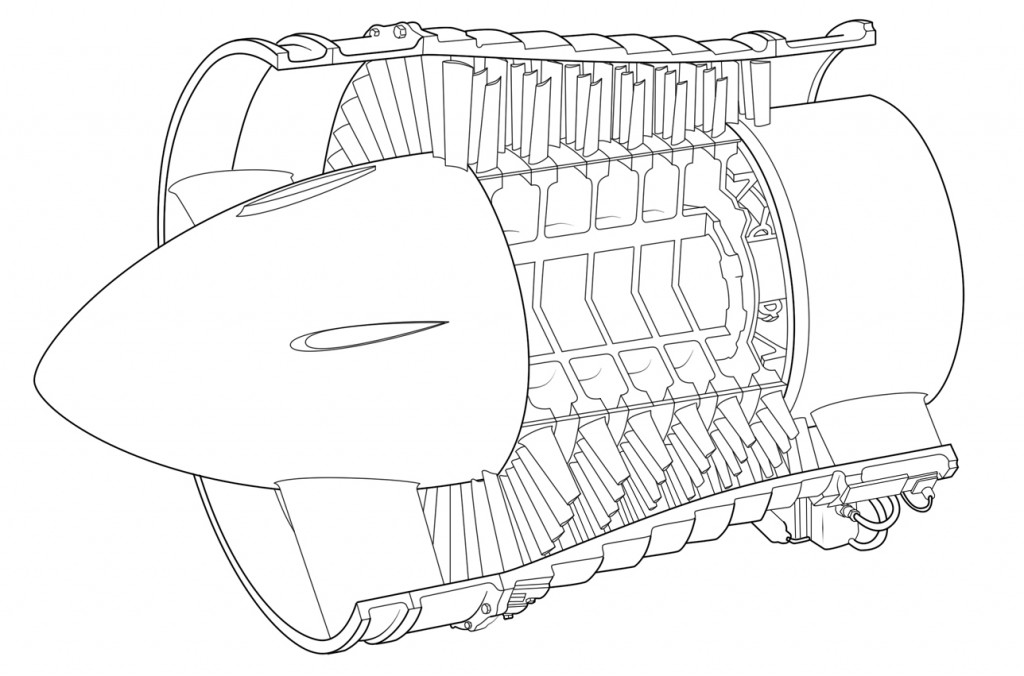
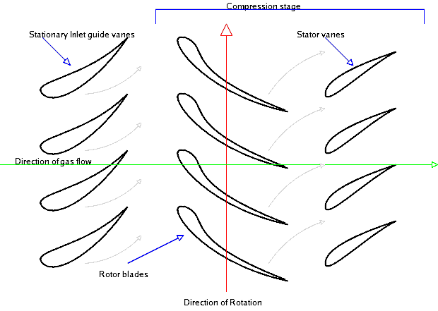
Because the pressure rises in the direction of flow through the compressor there is an acute risk of the boundary layers separating on the compressor blades as they encounter this adverse pressure gradient. When this happens the performance of the compressor drops dramatically and compressor is said to stall. For this reason the compression is spread over a large number of compressor stages such that the smaller incremental increases in pressure across each stage allow engineers to obtain a large overall pressure ratio without incurring stall. A stage consists of a row of rotating blades called the rotor and a row of stationary blades called the stator. Each of these rows may consist of between 30–100 distinct blades and there may be up to 20 stages between the air inlet and compressor outlet. The role of the rotor blades is to accelerate the incoming air in order to increase the kinetic energy of the fluid. Across the stators the fluid is then decelerated and as a consequence the fluid pressure is increased. As the pressure and density increase across each stage the overall flow velocity is kept relatively constant by reducing the height of the blades from stage to stage. Thus the compressor tapers down from inlet to outlet.
In an attempt to reduce the number of compressor stages for a more compact engine, a designer’s goal is to maximise the pressure ratio across each stage. The stage pressure ratio is given by the following expression,
Where is the stage isentropic efficiency, is the total (stagnation) temperature, the rotary speed of the compressor, the axial speed of the fluid, the coefficient of latent fusion at constant pressure, and and the angle of the rotor blade leading and trailing edge relative to the axial flow direction.
The pressure ratio across each stage can be maximised by increasing the rotary speed of the compressor , the angle through which the fluid is turned across the rotor blades and the axial speed of the fluid through the compressor. However there is a limit on the extent of these three parameters.
1. The blade tip speed and therefore is limited by stress considerations at the root. If the fan is assumed to be of constant cross-sectional area then the centrifugal stress at the root is given by,
Where is the tip speed, is the density of the blade, and the ratio is called the root-to-tip ratio of the blade. To prevent the blades from detaching from the hub and destroying the engine this root stress is not allowed to exceed a certain proof stress. It can be seen that the root stress is proportional to the square of the compressor rotational velocity and decreases as the blade length becomes shorter. Since the first compressor blades have the highest blade lengths they limit the maximum tip speed and therefore the efficiency of the compressor. It is therefore common to split the compressor into double or triple spool configurations such as a large fan, intermediate-pressure and high-pressure compressors that are rotating at three different speeds. In this manner the large diameter fan can rotate at lower speeds to satisfy the stress restrictions while the shorter blade high-pressure compressor may rotate at higher speeds.
However the rotational speed of the fan is typically constrained by more stringent stress considerations. In a turbofan engine the large diameter fan at the front of the engine acts as a single-stage compressor. In modern turbofan engines the fan divides the flow with most of the air going to the bypass duct to a propelling nozzle and only a small portion going into the core. The high root stresses caused by the long fan blades are often exacerbated by bird strikes. For mechanical reasons a lower limit of root-to-tip ratio of 0.35 is often employed. The flow impinging onto the fan is also at a very high Mach number since the cruising speed of civil aircraft is typically around M = 0.83. Supersonic flow inevitably terminates in a shock wave with a resulting increase in pressure and entropy over the compressor blades. Shock waves reduce the efficiency of the compressor blades since they disturb the flow over the profile that lead to boundary layer separation. Furthermore, these shock waves may cause unwanted vibrations of the fan blades that further reduce the efficiency of the compressor and increase noise. Therefore for reasons of efficiency, reducing noise and limiting the damage of bird strikes the tip speed of the fan is restricted, typically a relative Mach number of 1.6 is considered as the upper limit.
2. The axial speed has to be maximised to optimise the pressure ratio and reduce the frontal area of the engine. Similar to the argument given above the axial speed is typically limited by compressibility effects of supersonic flow. As the pressure, static temperature and therefore the speed of sound increases from stage to stage, the compressibility effects are worst in the first stages. For the first stage the air enters axially such that by adding the orthogonal velocity vectors and we get where V is the speed relative to the blade. In modern engines may be in the transonic region incurring quite large losses. In this respect twin-spool engines have the advantage that the lower-pressure compressor rotates at a lower speed, which reduces the compressibility problem.
3. The angle through which the fluid is turned across the rotor blades b is limited by the growth of the boundary layers. Compressor blades are aerofoils that function in the same manner as aeroplane wings. Therefore as the angle of attack or camber of aerofoil is increased to increase the rotation of the flow velocity vector, the adverse pressure gradient across the suction surface increases, until at some point the boundary layer separates. As the boundary layer separates the effective turning angle b is reduced such that the total pressure increase across the stage reduces.
The limits of , and all place limits on the maximum pressure ratio that can be achieved in an axial compressor. Typical examples are 350 m/s, = 200 m/s, 45°.
Compressor blades are typically quite thin and are constructed from lightweight metallic alloys such as aluminium and titanium. The compressor blades feature an aerofoil section as shown in the Figure below. The centrifugal forces that act on the airflow are balanced by high-pressure air towards the tip of the blade. In order to obtain this higher pressure towards the tip the blade must be twisted from root to tip in order to change the angle of incidence on the flow, and therefore control the pressure variation over the blade.
Key References
Rolls-Royce (1996). The Jet Engine. Rolls Royce Technical Publications; 5th ed. edition
Leave a Reply