Tag: wings

  • The Mystery of Wing Twisting

    The technological jump from no functional aeroplane to the first serious military fighter occurred in a mere 10 years. The Wright brothers conducted their first flight in late 1903 and by 1914 WWI broke out with an associated expansion in military flying. This expansion occurred almost entirely without the benefits of organised science in formal institutions and universities, and was led predominantly by tinkering aviators. Aircraft pioneers were often gifted flying-buffs or sporting daredevils, but very few of them had any real theoretical knowledge. This proved to be sufficient for the early developments, when flying was mostly a matter of strapping a powerful and lightweight engine to a basic flying design, and having the skills to keep the aircraft aloft and stable. Many pioneers, like Charles Rolls, paid with their lives for this mindset and it took many accidents from stalls and spins to figure out that something was amiss.

    The specifications and operating environment of aeroplanes was, of course, entirely different from either cars or trains. Particularly the design requirements for reliable yet lightweight construction posed a conundrum for early aerospace engineers. To make something stronger, a rule of thumb is to add more material. For aircraft this means increasing the wall-thickness of the beams, frames and plates that comprise the aircraft. Of course, by making components thicker, the structure becomes heavier and less likely to fly. Furthermore, thicker structures are stiffer, which causes loads to be redirected within the structure, and rather counter-intuitively, can make the aircraft more likely to fail.

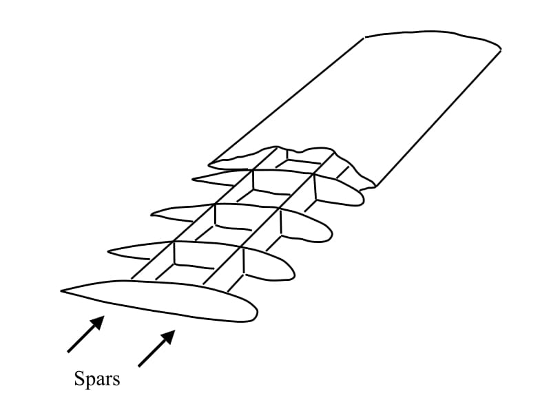
    This counter-intuitive finding was played-out during the discovery of wing twisting. Wings are predominantly subject to bending forces due to aerodynamic lift that keeps the aircraft aloft. As this is entirely obvious, and since there was a great deal of acquired expertise in bridge building, wing bending loads were supported quite reliably by beams (spars) running along the length of the wing. The wing is, however, also subject to large twisting forces, and if these are not accounted for, the wing will twist-off the fuselage.

    Spars running along the length of the wing and connected by a series of ribs

    By 1917, the Allies had developed a certain degree of air superiority over the Western Front of WWI by means of better biplane construction. Out of necessity the Dutch engineer Anthony Fokker, working in Germany at the time, was developing a more advanced monoplane design with performance specifications better than anything the Allies had to offer. While biplanes are very light and were the preferred type of construction up to that point, their flying performance in terms of nimbleness and speed is limited due to the high drag induced by the aerodynamic interference of the two separate wings. There was thus a strong incentive to build faster monoplane aeroplanes. But since the fateful crash of Samuel Langley into the Potomac River in 1903, monoplanes had the reputation of being entirely unreliable.

    Fokker D8

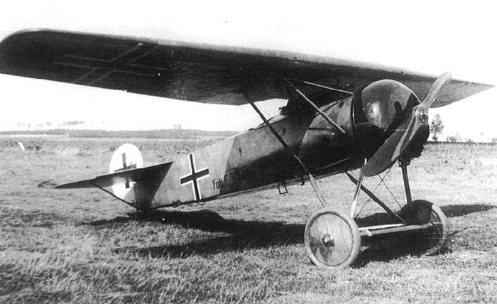
    And indeed, as soon as Fokker’s new D8 aeroplane flew in combat situations, the wings started to snap-off as pilots pulled out of dives during dogfights. Being pressed for time, the D8 hadn’t gone through an extensive series of flying tests, and this cost many of Germany’s best pilots their lives. As a result, the German Air Force ordered a series of structural tests on the D8. As in the more standard biplanes of the time, the wings of the D8 were entirely covered by a thin fabric whose only purpose was to provide an aerodynamic profile for lift creation. The fabric itself did not carry any of the aerodynamic loads, and indeed all wing-bending loads were carried by two spars projecting from the fuselage and running along the length of the wing. The spars were connected by a series of ribs which served as attachment points for the stretched fabric. According to the testing standards of the time, the D8 aircraft was mounted upside down with weights suspended from the wings to simulate aerodynamic loads six times the weight of the aircraft. When tested this way, the wings showed absolutely no sign of weakness. When increasing the load beyond the factor of six, the wings began to fail in the aft spar such that the German authorities ordered all rear spars to be replaced by thicker and stronger ones. Unfortunately for the German military command, the accidents of the D8 become more frequent as a result of this intervention. Germany’s engineers now faced the perplexing conundrum that adding more material to the wings seemingly made them weaker!

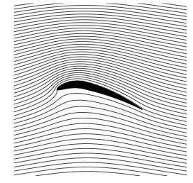
    At this point Fokker took matters into his own hands and repeated the tests in his own factory. What he found was that not only would the wings rise as a result of aerodynamic loads, but they would twist too, even though there was no obvious twisting loads being applied. Particularly important was the direction of twisting, which occurred as to twist the leading edge upwards, thereby increasing the angle of attack and the lift created by the wings, thus further increasing wing twisting, and so on in a detrimental feedback loop. As a pilot pulled up out of a dive, the extra lift needed to pull-off the manoeuvre was sufficient to initiate this catastrophic feedback loop, until the wings eventually twisted-off. Fokker had discovered the phenomenon now known as “divergence”.

    But why did this divergent behaviour occur in the first place?

    Imagine two horizontal and identical beams placed side by side and connected by a number ribs along their length to bridge the gap between them. One end of this assemblage is free and the other is rigidly supported (clamped). This simple construction is basically the fundamental structure of even the most modern aircraft. If a vertical load is applied exactly halfway between the two beams at the free end, then both beams will just bend upwards without any twist. However, if the vertical load is biased towards one of the beams then the assemblage will bend and twist at the same time, because the load carried by one beam is greater than the load carried by the other. The point where a load must be applied such that a structure bends without twisting is known as the flexural centre.

    If a load is applied at the flexural centre (for a wing pretty much half-way between the two spars) the wing will only bend. But because the centre of pressure is located at the quarter-chord position, the wing bends and twists at the same time. The load is not applied at the flexural centre

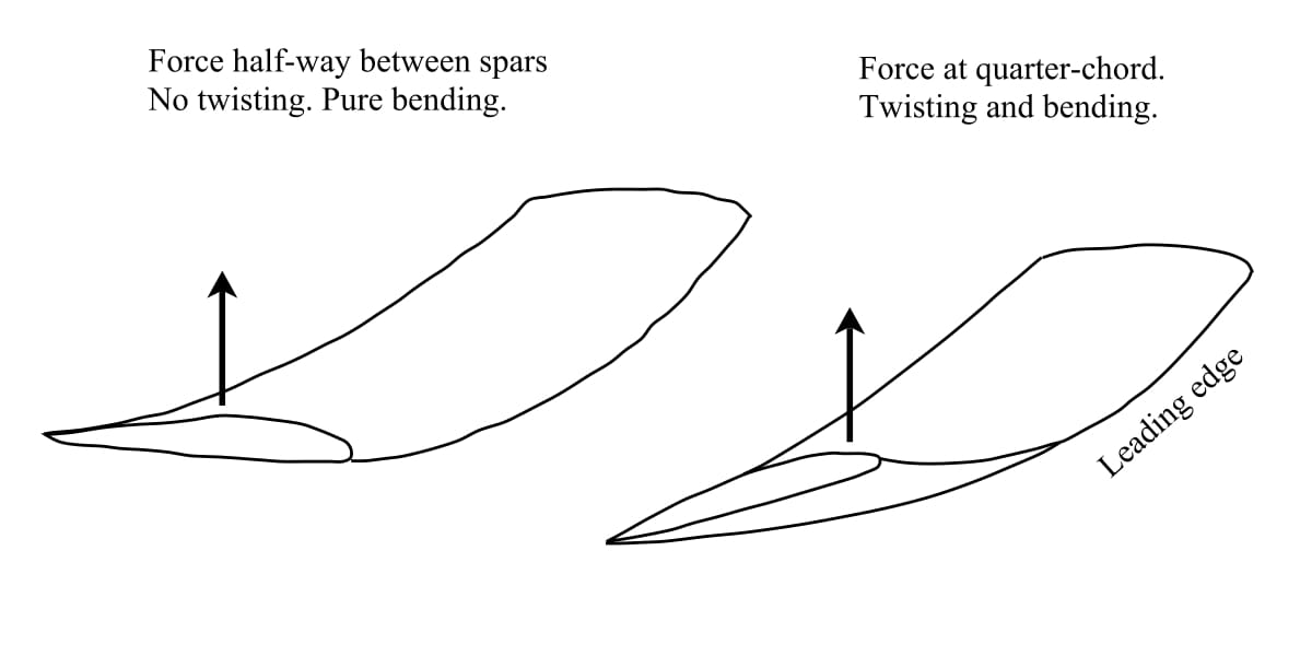
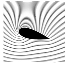
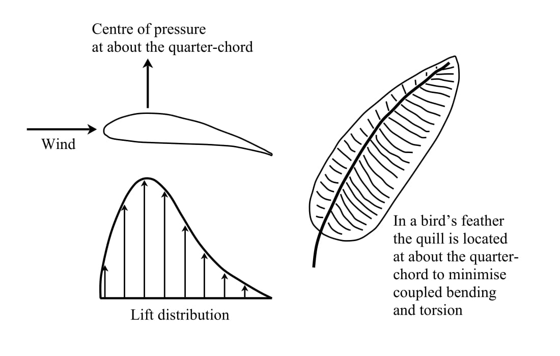
    Of course, if there are more than two beams or if the beams are of different stiffness, then the flexural centre will not be halfway between the beams. In fact, the aerodynamic lift forces are distributed across the wing and do not really act at a single point. However, the distribution of aerodynamic pressure can be summed up and represented mathematically as acting as a point load somewhere between the front and rear spars. This point is known as the centre of pressure and may shift along the length of the wing. One might assume that the centre of pressure of a wing profile is situated nicely in the middle of the two spars, but this is not what happens. The centre of pressure for most wing profiles is in fact just behind the front spar, in the vicinity of the quarter-chord position, that is 25% of the chord length behind the leading edge. Therefore it follows quite simply that if the flexural centre and centre of pressure do not coincide, the wing must twist and bend at the same time. The extent of twisting naturally depends on this mismatch and the stiffness of construction in torsion. It is the designer’s role to minimise it as much as possible, and in fact, the thick quill of a bird’s feather is located at about the quarter span to minimise twisting.

    Wing lift distribution with centre of pressure at the quarter-chord. A feather features a reinforcing “spar” at the quarter-chord to prevent twisting of the feathers

    In the simple fabric-covered D8 monoplane, the flexural centre and torsional stiffness of the wing depended entirely on the two wing spars. In early designs of the D8, the centre of flexure was pretty much bang in the middle between the two spars, and the fruitless attempts of beefing-up the rear spar only moved the flexural centre further to the rear and away from the centre of pressure at the quarter chord. So Fokker decided to reduce the thickness of the rear spar, thereby not only solving the problem of divergence but also making the aircraft lighter and a serious menace to the British and French biplanes.

    Fokker also came up with a second design evolution that enabled monoplanes. In the early fabric-covered monoplanes the torsional stiffness of the wing is provided entirely by differential bending of the two spars. Not much can be done to improve the torsional stiffness by tinkering with the design of these spars. This was part of the reason why monoplanes were forbidden in the early days of flying. It was a safety precaution, and not a particularly unpopular one, because in practise many biplanes were not much slower than monoplanes and considerably more reliable.

    An example of the shear flow around a wing box due to a vertically applied load

    As a structure is sheared it creates what is called shear flow – the shearing force divided by the length of material over which it acts. Because the fabric does not carry sufficient loading, the early fabric-covered monoplane construction is considered an “open” cross-section as shear cannot flow from one spar to the other. The strutted and braced construction of the biplane, however, has the advantage of creating a closed “torsion box”. The torsion box of biplanes creates a closed cross-section and the shearing forces can flow around the material to optimally resist torsion. Torsion is therefore ideally resisted by any box or tube whose sides are continuous. The second breakthrough of monoplane construction was therefore to replace the fabric with thicker sheet-metal that could carry load. Now the closed aerodynamic surface of the wing could provide the job of resisting shear loads efficiently, while the two spars predominantly served to resist bending loads. In effect, this is an efficient division of labour concept even though it requires a much thicker and heavier wing to resist torsion.

    References
    [1] J.E. Gordon. Structures: Or Why Things Don’t Fall Down. DeCapo Press. 2nd Edition, 2003.

  • What Creates Lift – How Do Wings Work?

    How airplanes fly is one of the most fundamental questions in aerospace engineering. Given its importance to flight, it is surprising how many different and oftentimes wrong explanations are being perpetuated online and in textbooks. Just throughout my time in school and university, I have been confronted with several different explanations of how wings create lift.

    Most importantly, the equal transit time theory, explained further below, is taught in many school textbooks and therefore instils faulty intuitions about lift very early on. This is not necessarily because more advanced theories are harder to understand or require a lot maths. In fact, the theory that requires the simplest assumptions and least abstraction is typically considered to be the most useful.

    In science, the simplicity of a theory is a hallmark of its elegance. According to Einstein (or Louis Zukofsky or Roger Sessions or William of Ockham…I give up, who knows), “everything should be made as simple as possible, but not simpler.” Hence, the strength of a theory is related to:

    • The simplicity of its assumptions, ideally as few as possible.
    • The diversity of phenomena the theory can explain, including phenomena that other theories could not explain.

    Keeping this definition in mind, let’s investigate some popular theories about how aircraft create lift.

    The first explanation of lift that I came across as a middle school student was the theory of “Equal Transit Times”. This theory assumes that the individual packets of air flowing across the top and bottom surfaces must reach the trailing edge of the airfoil at the same time. For this to occur, the airflow over the longer top surface must be travelling faster than the air flowing over the bottom surface. Bernoulli’s principle, i.e. along a streamline an increasing pressure gradient causes the flow speed to decrease and vice versa, is then invoked to deduce that the speed differential creates a pressure differential between the top and bottom surfaces, which invariably pushes the wing up. This explanation has a number of fallacies:

    • There is no physical law that requires equal transit times, i.e. the underlying assumptions are certainly not as simple as possible.
    • It fails to explain why aircraft can fly upside down, i.e. does not explain all phenomena.

    As this video shows, the air over the top surface does indeed flow faster than on the bottom surface, but the flows certainly do not reach the trailing edge at the same time. Hence, this theory of equal transit times is often referred to as the “Equal Transit Time Fallacy”.

    In order to generalise the above theory, while maintaining the mathematical relationship between speed and pressure given by Bernoulli’s principle, we can relax the initial assumption of equal transit time. If we start from a phenomenological observation of streamlines around an airfoil, as depicted schematically below, we see can see that the streamlines are bunched together towards the top surface of the leading edge, and spread apart towards the bottom surface of the leading edge. The flow between two adjacent streamlines is often called a streamtube, and the upper and lower streamtubes are highlighted in shades of blue in the figure below. The definition of a streamline is the line a fluid particle would traverse as it flows through space, and thus, by definition, fluid can never cross a streamline. As two adjacent streamlines form the boundaries of the streamtubes, the mass flow rate through each streamtube must be conserved, i.e. no fluid enters from the outside, and no fluid particles are created or destroyed. To conserve the mass flow rate in the upper streamline as it becomes narrower, the fluid must flow faster. Similarly, to conserve the mass flow rate in the lower streamtube as it widens, the fluid must slow down. Hence, in accordance with the speed-pressure relationship of Bernoulli’s principle, this constriction of the streamtubes means that we have a net pressure differential that generates a lift force.

    Flow lines around a NACA 0012 airfoil at 11° angle of attack, with upper and lower streamtubes identified.

    Of course, this theory does not explain why the upper streamtube contracts and the lower streamtube expands in the first place. An intuitive explanation for this involves the argument that the angle of attack obstructs the flow more towards the bottom of the airfoil than towards the top. However, this does not explain how asymmetric airfoils with pronounced positive camber at zero angle of attack, as shown in the figure below, create lift. In fact, such profiles were successfully used on early aircraft due to their resemblance to bird wings. Again, this theory does not explain all the physical phenomena we would like it to explain, and is therefore not the rigorous theory we are looking for.

    Asymmetric airfoil with pronounced camber
    Asymmetric airfoil with pronounced camber [1]

    Another explanation that is often cited for explaining lift is that the airfoil pushes air downwards, i.e. there is a net change of momentum in the vertical plane between the leading and trailing edges of the airfoil, and by necessity of Newton’s third law, this creates a lift force. Any object that experiences lift must certainly conform to the reality of Newton’s third law, but referring only to the difference in start and end conditions ignores the potential complexity of flow that occurs between these two stations. Furthermore, the question remains through what net angle the flow is deflected? One straightforward answer is the angle of incidence of the airfoil, but this ignores the upwash ahead of the wing or anything that happens behind the wing. Hence, the simple explanation of “pushing air downwards”, however elegant and correct, is an integral approach that summates the fluid mechanics between leading and trailing edges and leaves little to say of what happens in between. Indeed, as will be shown below, upwash and flow circulation play an equally important role in creating lift.

    Indeed, we can imagine a flow around a 2D cylinder shown in the figure below. The flow is symmetric from left-to-right and top-to-bottom and experiences no lift. If we now start the cylinder spinning at the rate Ω\Omega in the clockwise direction shown, the velocity of air increases on the upper surface (reduced pressure) and reduces on the lower surface (higher pressure). This asymmetric flow top-to-bottom therefore creates lift. Note that the rotation of the cylinder has moved the stagnation point towards the rear end of the cylinder (where the bottom and top flows converge) downwards and therefore broken the symmetry of the flow. Hence, in this example, lift is created by a combination of a free-stream velocity and flow circulation, i.e. air is “spun up” and not necessarily just deflected downwards (in this example upwash ahead of the cylinder matches the downwash aft).

    Flow around a cylinder
    Flow around a rotating cylinder that induces lift

    In the example above, lift was induced by creating an asymmetry in the curvature of the streamlines. In the stationary cylinder we had streamlines curving in one direction on the top surface, and by the same amount in the opposite direction on the bottom surface. Rotating the cylinder created an asymmetry in streamline curvature between the top and bottom surfaces (more curvature upwards then curvature downwards). We can create a similar asymmetry in the flow with a stationary cylinder by placing a small sharp-edged flap at the rear edge and positioned slightly downwards. Real viscous flow might not necessarily flow as smoothly around the little flap as shown in the diagram below, but this mental model is a neat tool to imagine how we can morphologically transition from a rotating cylinder that produces lift to an airfoil. This is shown via the series of diagrams below. This series of pictures shows that an airfoil creates a smoother variation in velocity than the cylinder, which leads to a smaller chance of boundary layer separation (a source of drag and in the worst-case scenario aerodynamic stall). A similar streamline profile could also be created with a symmetric airfoil that introduces asymmetry into the flow by being positioned at a positive angle of attack.

    The reason why differences in streamline curvature induce lift is addressed in a journal paper by Prof Holger Babinsky, which is free to download. If we consider purely stead-state flow and neglect the effects of gravity, surface tension and friction we can derive some very basic, yet insightful, equations that explain the induced pressure difference. Quite intuitively this argument shows that a force acting parallel to a streamline causes the flow to accelerate or decelerate along its tangential path, whereas a force acting perpendicular to the flow direction causes the streamline to curve.

    The first case is described mathematically by Bernoulli’s principle and depicted in the figure below. If we imagine a small fluid particle of finite length l situated in a field of varying pressure, then the front and back surfaces of the particle will experience different pressures. Say the pressure increases along the streamline, then the force acting on the front face pointing in the direction of motion is greater than the force acting on the rear surface. Hence, according to Newton’s second law, this increasing pressure field along the streamline causes the flow speed to decrease and vice versa. However, this approach is valid only along a single streamline. Bernoulli’s principle can not be used to relate the speed and pressures of adjacent streamlines. Thus, we can not use Bernoulli’s principle to compare the flows on the bottom and top surfaces of an airfoil, and therefore can say little about their relative pressures and speeds.

    Flow along a straight streamline [2]
    Flow along a straight streamline [2]

    However, consider the curved streamlines shown in the figure below. If we assume that the speed of the particle travelling along the curved streamline is constant, then Bernoulli’s principle states that the pressure along the streamline can not change either. However, the velocity vector v is changing, as the direction of travel is changing along the streamline. According to Newton’s second law, this change in velocity, i.e. acceleration, must be caused by a net centripetal force acting perpendicular to the direction of the flow. This net centripetal force must be caused by a pressure differential on either side of the particle as we have ignored the influence of gravity and friction. Hence, a curved streamline implies a pressure differential across it, with the pressure decreasing towards the centre of curvature.

    Flow along a curved streamline [2]
    Flow along a curved streamline [2]

    Mathematically, the pressure difference across a streamline in the direction n pointing outwards from the centre of curvature is

    dpdn=ρv2R\frac{\mathrm{d}p}{\mathrm{d}n} = \rho \frac{v^2}{R}

    where R is the radius of curvature of the flow and ρ\rho is the density of the fluid.

    One positive characteristic of this theory is that it explains other phenomena outside our interest in airfoils. Vortices, such as tornados, consist of concentric circles of streamlines, which suggests that the pressure decreases as we move from the outside to the core of the vortex. This observation agrees with our intuitive understanding of tornados sucking objects into the sky.

    With this understanding we can now return to the study of airfoils. Consider the simple flow path along a curved plate shown in the figure below. At point A the flow field is unperturbed by the presence of the airflow and the local pressure is equal to the atmospheric pressure patmp_{atm}. As we move down along the dashed curve we see that the flow starts to curve around the curved plate. Hence, the pressure is decreasing as we move closer to the airfoil surface and pB<patmp_B < p_{atm}. On the bottom half the situation is reversed. Point C is again undisturbed by the airflow but the flow is increasingly curved as me closer to D. However, when moving from C to D, the pressure is increasing because pressure increases moving away from the centre of curvature, which on the bottom of the airfoil is towards point C. Thus, pD>patmp_D > p_{atm} and by the transitive property pB<pDp_B < p_D such that the airfoil experiences a net upward lift force.

    Flow around a curved airfoil [2]
    Flow around a curved airfoil [2]

    From this exposition we learn that any shape that creates asymmetric curvature in the flow field can generate lift. Even though friction has been neglected in this analysis, it is crucial in forcing the fluid to adhere to the surfaces of the airfoil via a viscous boundary layer. Therefore, the inclusion of friction does not change the theory of lift due to streamline curvature, but provides an explanation for why the streamlines are curved in the first place.

    A couple of interesting observations follow from the above discussion. Nature typically uses thin wings with high camber, whereas man-made flying machines typically have thicker airfoils due to their improved structural performance, i.e. stiffness. In the figure below, the deep camber thinner wing shows highly curved flow in the same direction on both the top and bottom surfaces.

    Deep camber thin wing with high lift [2]
    Shallow camber thick wing with less lift [2]

    The more shallow camber thicker wing has flow curved in two different directions on the bottom surface and will therefore result in less pressure difference between the top and bottom surfaces. Thus, for maximum lift, the thin, deeply cambered airfoils used by birds are the optimum configuration.

    In conclusion, we have investigated a number of different theories explaining how lift is created around airfoils. Each theory was investigated in terms of the simplicity and validity of its underlying assumptions, and the diversity of phenomena it can describe. The theories based on Bernoulli’s principle, such as the equal transit time theory and the contraction of streamtubes theory, were either based on faulty initial assumptions, i.e. equal time, or failed to explain why streamtubes should contract or expand in the first place. The theory based on airfoils deflecting airflow downwards is theoretically accurate and correct (Newton’s third law: changes in fluid momentum over a control volume including the airfoil lead to a reactive lift force), but by being an integral approach it is not helpful in explaining what occurs between the leading and trailing edges of the airfoil (e.g. upwash is also a contributing factor to lift).

    A more intricate theory is that curved bodies induce curved streamlines, as the inherent viscosity of the fluid forces the fluid to adhere to the surface of the body via a boundary layer. The centripetal forces that arise in the curved flow lead to a drop in pressure across the streamlines towards the centre of curvature. This means that if a body leads to asymmetric curved streamlines across it, then the induced pressure differential arising from the asymmetry induces a net lift force.

    Edits and Acknowledgments

    A previous version of this article referenced a misleading and incorrect example of a highly cambered airfoil as a counterexample to the theory of airfoils deflecting airflow downwards and the theoretical explanation using control volumes. Dr Thomas Albrecht of Monash University pointed this error out to me (see the discussion in the comments) and his contribution in improving the article is gratefully acknowledged.

    Photo credit

    [1] DThanhvp. Photobucket. http://s37.photobucket.com/user/DThanhvp/media/American.jpg.html

    [2] Babinsky, H. (2003). How do wings work?. Physics Education 38(6) pp. 497-503. URL: http://iopscience.iop.org/article/10.1088/0031-9120/38/6/001/pdf;jsessionid=64686DBCB81FEB401CFFB87E18DFE6DA.c1