Tag: structures

  • Antifragility and Aircraft Design

    Nassim Nicholas Taleb coined the term “Antifragility” in his book of the same name. Antifragility describes objects that gain from random perturbations, i.e. disorder. Taleb writes,

    Some things benefit from shocks; they thrive and grow when exposed to volatility, randomness, disorder, and stressors and love adventure , risk, and uncertainty. Yet, in spite of the ubiquity of the phenomenon, there is no word for the exact opposite of fragile. Let us call it antifragile. Antifragility is beyond resilience or robustness. The resilient resists shocks and stays the same; the antifragile gets better. This property is behind everything that has changed with time: evolution, culture, ideas, revolutions, political systems, technological innovation, cultural and economic success, corporate survival, good recipes (say, chicken soup or steak tartare with a drop of cognac), the rise of cities, cultures, legal systems, equatorial forests, bacterial resistance … even our own existence as a species on this planet. And antifragility determines the boundary between what is living and organic (or complex), say, the human body, and what is inert, say, a physical object like the stapler on your desk.

    In greek mythology the sword of Damocles is an example of a fragile object as a single large blow will break it, a phoenix can resurrect and is therefore robust, while the Hydra is an antifragile serpent because for every head that is chopped off, two will grow back in its place. Antifragile systems are extremely important in complex environments where black swan events can wreak havoc. Black swans are rare but highly consequential events; the “fat tails” located far away from the mean in a probability distribution.

    Often black swan events happen due to non-linear behaviour or a confluence of multiple drivers. Non-linearity is inherently difficult for our brains to comprehend which makes black swan events basically impossible to predict beforehandIn structural mechanics for example, it took researchers years to realise that the buckling behaviour of cylindrical shells, such as fuselage sections, is an inherently non-linear structural phenomenon, and that linear eigenvalue solutions could result in drastic over-predictions of the load carrying capacity. Theodore von Kármán managed to explain the physics of the problem through a series of papers in the first half of the 20th century, by first qualitatively investigating the phenomenon using simple experiments and then formalising the theory in what are now the non-linear von Kármán equations.

    But what does this have to do with the engineering design process?

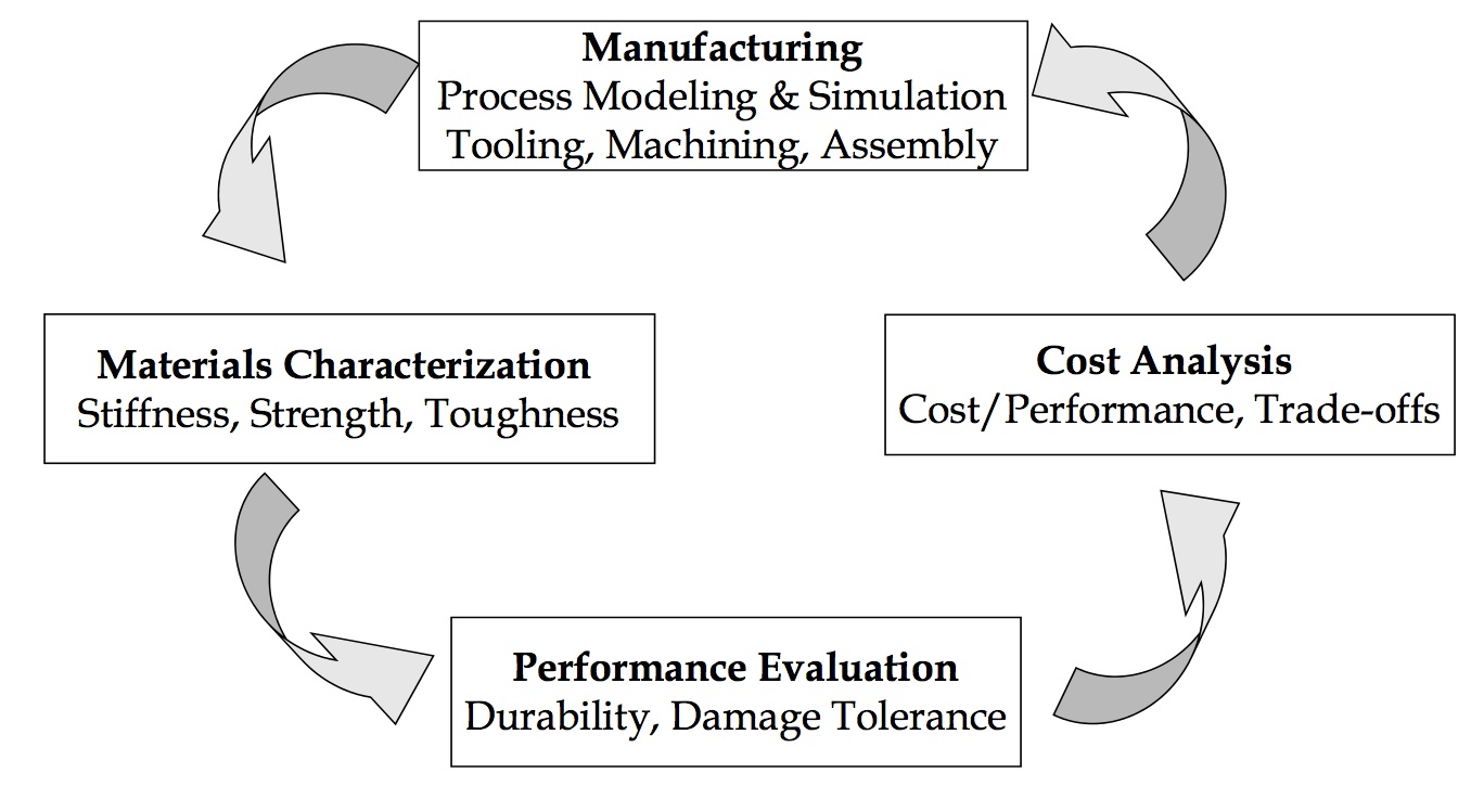
    Well, by nature the design process is iterative. Ideally we strive towards creating a system of concurrent engineering. Tasks performed by the design, structural and manufacturing engineers are parallelised and integrated to reduce the development time to market, and reach the best compromise between different technical and financial requirements. Despite this parallelisation, the design process within each of these departments is still highly iterative as engineers across different functional fields interact and refine the design. Most importantly, throughout the whole aircraft design process individual components and sub-assemblies are experimentally tested to verify the design under critical load conditions. Examples of these are cabin section pressurisation fatigue tests and catastrophic tests of whole wing sub-assemblies. The information of these stress tests is fed back into the design system to close the loop and inform the next stage in the design.

    Design Cycle Structural Engineering
    Design Cycle Structural Engineering

    Taleb calls this form innovative work “stochastic tinkering”. It is a means of experimenting and adjusting a system, aiming to discover fact “A” but in the process also learning about “B”. Stochastic tinkering is by nature antifragile as good aspects of a design are retained while failures are quickly removed; very much an analog of the evolutionary process in nature.

    Of course there is a good deal of deterministic analysis involved in engineering design. However, preliminary design calculations are often based on “back-of-the-envelope” methods. The aim of these preliminary calculations is to constrain the design space to a smaller feasible region. The design is then refined further in the detail design stage using more advanced techniques such as Finite Element Analysis or Computational Fluid Mechanics. Crucially, no matter how beautiful the design works on paper if it doesn’t perform in the validation tests it has failed.

    Finally, the notion of designing for black swan events is inherently incorporated in the design process. In structural analysis of aircraft hundreds of different load cases are tested individually and in confluence to make sure the structure can withstand the worst imaginable/historic loading scenario multiplied by a factor of safety. Furthermore, the “safe-life”, “fail-safe” and “damage tolerant” design frameworks create a checklist for components which:

    • are absolutely not allowed to fail during service (e.g. landing gear and wing root)
    • are allowed to fail, as structural redundancies are in place to re-direct load paths (e.g. wing stringers and engines)
    • and components that are assumed to contain a finite initial defect size before entering service that may grow due to fatigue loading in-service. In this manner the aircraft structure is designed to sustain structural damage without compromising safety up to a critical damage size that can be easily detected by visual inspection between flights. 

    This approach is limited to known load cases. Therefore, the reserve factors of 1.2 for limit load and 1.5 for ultimate load exist to provide a margin of safety against uncertainty, i.e. things we can not quantify, the “known unknowns” and “unknown unknowns”.

    Historically, catastrophic in-service failures have been and continue to be used as invaluable learning experiences. Thus, “fat tail” catastrophic events are continually being used to eradicate weaknesses and improve the design. This, in essence, is the definition of antifragility. As terrible as the loss of life in the DeHavilland Comet and other crashes have been, without them, airplane travel would not be as safe as it is today.

  • Fancy a Sandwich?

    In this post I want to use the sandwich panel as an example to explain some basic concepts about bending of structures. The explanations in this post are kept very basic and are similar to a first semester course in structural mechanics. Sandwich panels are an important composite structure in aerospace applications as well as in high performance automobiles, boats and wind turbines. Typically a sandwich panel is comprised of a low stiffness, low density inner core enclosed by two stiff outer skins, as shown in Figure 1, where the whole assembly is held together by some sort of structural adhesive (Figure 2). The outer skins are typically made from stiff carbon fibre or aerospace grade aluminium.

    Fig. 1. A honeycomb carbon fibre sandwich panel (1)
    Fig. 1. A honeycomb carbon fibre sandwich panel (1)
    Fig. 2. Sandwich panel components and construction
    Fig. 2. Sandwich panel components and construction

    The inner core is typically a Nomex or metal honeycomb, or an open or closed cell foam. Nomex is an aramid polymer similar to Nylon that is flame-resistant and can be manufactured in paper sheet form. Nomex is a great choice for the interior of aircraft cabins such as the floor panels due to its high safety in the event of fire. Multiple sheets of Nomex paper can be placed on top of each other and glued together at the node locations by lines of adhesive, which are offset spatially between different layers. This large stack of Nomex can then be cut into smaller strips and expanded to form a sheet of Nomex honeycomb. Alternatively closed cell foams such as Rohacell® are commonly used for the core, which are denser then there open cell counterparts but prevent moisture ingress in service and have better mechanical properties.

    Fig. 2. Manufacture of a honeycomb sheet (2)
    Fig. 3. Manufacture of a honeycomb sheet (2)

    But what is the advantage of using a sandwich panel?

    Various structures on an aeroplane are subjected to bending loads. Essentially the bending of a beam or a plate, by say some sort of pressure loading over its surface, is equivalent to grabbing the edges and applying a moment or rotation. Under pure bending Engineer’s bending theory assumes that the structure resists this moment by a linear variation of stress through its thickness. Thus, the maximum stresses occur at the top and bottom surfaces, one being compressive and the other tensile, while the stress at the middle of the beam thickness is zero. This unstressed location is called the neutral axis. For pure bending the neutral axis is always located at the centroid of the cross-section (the mid-plane for a rectangular cross-section) and can be calculated using the integral expression for the first moment of area. Therefore we can see that that the structure balances the externally applied bending moment by an internal force couple of equal magnitude where the fulcrum of the couple is the location of the neutral axis.

    Fig. 3. Bending moment and internal stress distribution of beam under pure bending (3)
    Fig. 4. Bending moment and internal stress distribution of beam under pure bending (3)

    However this linear variation of stress is not very efficient since the cross-section of the beam is not uniformly stressed i.e. it would be more efficient if the whole cross-section was constantly loaded by the average stress to spread out the load. One method to improve the design is to cut-out the material close to the neutral axis in order to reduce structural mass as shown in Figure 5. Another possibility is to use a sandwich panel i.e. place stronger material towards the outside where it is needed and replace the interior section with a less dense and therefore lighter (and generally weaker) material to save weight.

    Fig. 4. Fuselage frame with flared holes (4)
    Fig. 5. Fuselage frame with flared holes (4)

    A major advantage of the sandwich construction compared to the flared hole design is that the core separates the stiff outer skins, placing them as far as possible from the neutral axis. The degree in which a structure prevents deflection in bending is known as the bending rigidity EI, where E is the Young’s modulus or stiffness of the material used and I is the second moment of area. The second moment of area I, which is the bending resistance of the cross-section, increases the more mass is located away from the neutral axis. This is analogous to rotational motion where the inertia of rotation increases the further away the rotating mass is located from the centre of rotation. In fact, as the name “second moment of area” suggests, the bending resistance increases with the square of the distance from the neutral axis. Thus a sandwich panel moves two stiff skins (high values of E such as Carbon fibre laminates) far away from the central neutral axis in order to maximise the product EI and therefore create a structure of incredibly high specific flexural stiffness i.e. high bending stiffness coupled with minimum mass. The improvements of stiffness versus weight of a sandwich panel by increasing the separation of the two face sheets is clearly illustrated in Figure 6. Here the density of the face sheets is assumed to be 15 times higher than that of the core.

    Fig. 5. Stiffess vs. weight comparison for a sandwich panel
    Fig. 6. Stiffness vs. weight comparison for a sandwich panel

    Apart from increasing the bending rigidity another advantage of using sandwich panels is that it actually concentrates the direct bending stresses (axial σxx,σyy\sigma_{xx}, \sigma_{yy} and shear τxy\tau_{xy}) in the face sheets. This is because when a structure deforms the load always distributes relative to the stiffness of the different parts. For example, when two springs are aligned in parallel and fixed on one end by a support and are displaced by the same extension on the other end the load taken by spring 1 will be twice as high as that by spring 2 if k1=2k2k_1 = 2*k_2.

    Fig. 6. Two springs in parallel (5)
    Fig. 7. Two springs in parallel (5)

    This is equivalent what happens to in a sandwich beam. Since the face sheets have much higher Young’s modulii than the low-density core, in bending the large majority of the direct bending loads is actually taken by the face sheets. This means that the stress distribution is no longer continuously linear through the entire cross-section as for an isotropic material in Figure 4, but actually piecewise linear and discontinuous at the interfaces. For example Figure 8 below clearly indicates how the variation of stress through the thickness of the sandwich panel changes as the stiffness mismatch between the core and face sheets is increased. As the modulus of the skins reaches 50 times that of the core there is a large jump in bending stress from just over zero to about 2 MPa. Compared to the case of equal Young’s modulus this solution is much more efficient since both the skins and the core are more uniformly stressed. The limitation of this design is that the large discontinuity of bending stress at the interface may cause excessive transverse shear stresses at the interface that can literally pull the face skins away from the core and cause de-bonding of the two parts. This is why it is important to use a core with high transverse shear modulus and strength such as honeycomb to absorb these transverse shear loads. Furthermore, the core transverse shear strength is important for resisting point or distributed pressure loadings over the surface of the face sheets and give local support for fasteners.

    Fig. 7. In-plane stress profile through the thickness of a sandwich panel for various ratios of core-to-face sheet Young's modulus
    Fig. 8. In-plane stress profile through the thickness of a sandwich panel for various ratios of core-to-face sheet Young’s modulus

    Of course there are also many drawbacks of using sandwich panels. For example when using honeycomb cores it is very hard to form complex curved shapes using the standard hexagonal matrix shape. This is because honeycomb has very high values of Poisson’s ratio such that the anti-clastic curvature effects in bending are quite pronounced. This means that when the honeycomb is bent to adhere to a certain shape it will form opposite curvature in the perpendicular direction to form a saddle shape. During in service bending deformation this will also cause the centre of the core to want to pull away from the face sheets again leading to excessive transverse shear and normal stresses at the interface and possible de-bonding of the core and face sheets. In fact de-bonding may also occur due to impact events or slow moisture ingress into the open cell honeycomb structure during service. Furthermore, when not properly designed honeycomb cores may collapse under the external pressure loading when the sandwich panel is cured in the high-temperature and pressure oven known as an Autoclave. Some of these drawbacks can be overcome by using closed-cell forms such as Rohacell®, which have lower degrees of anti-clastic curvature and, being “closed-cell”, greatly reduce the danger of water ingress into the core. The drawback of these foams is that there intrinsic higher density makes them heavier than the equivalent honeycomb solution. Alternatively, different cellular core configurations other than honeycomb such as Flex-core, rectangular and square may be used to reduce the anti-clastic curvature problem.

    Fig. 7. Different cellular core styles
    Fig. 9. Different cellular core styles

    In metal construction the analogy to the sandwich beam is the I-beam seen in many civil constructions. Here the two flanges are located away from the neutral axis by the vertical web section. The difference in this design is that the vertical web section does also take considerable direct in-plane loads since it is of the same material and therefore stiffness as the two flanges. However, I-beams are much more cost-effective than sandwich beams since they can be easily mass-produced and do not suffer difficulties such as debonding between the face sheets and the core.

    In summary a sandwich comprises,

    • two stiff and lightweight face sheets that predominantly take in-plane stresses and shear loads
    • a low-density core that takes transverse shear loads, separates the face sheets for high bending rigidity, supports the face sheets against buckling modes forming and can give local support for fastener loads
    • an adhesive holding the entire assembly together which transfer shear loads to the core and keeps the skins in the correct location.

    References

    (1) http://img.nauticexpo.com/images_ne/photo-g/sandwich-panel-carbon-fiber-honeycomb-37057-385887.jpg

    (2) http://www.paneltech.biz/photos/honeycomb-corrugated.gif

    (3) http://www.learneasy.info/MDME/MEMmods/MEM30006A/Bending_Stress/Bending_Stress.html

    (4) http://www.williammaloney.com/Aviation/VintageWingsOfCanada/HawkerHurricane/images/37HurricaneFuselageFrame.jpg

    (5) http://scienceworld.wolfram.com/physics/simg476.gif