Stefan Brieschenk is the Chief Operating Officer of Rocket Factory Augsburg (RFA), a company in the south of Germany that is developing a low-cost launch vehicle. RFA’s vision is to drastically reduce the cost of access to space through large-scale industrialisation of their operations and manufacturing.
Key to RFA’s design approach is a holistic performance and cost optimisation tool that has been developed in collaboration with space industry veterans MT Aerospace and OHB. This approach has led to interesting design choices. For example, the second stage tank is based on inexpensive stainless steel construction, and in places where composite materials are being used, RFA is relying on automotive grade materials that have already been used in high-volume production. In their propulsive system, however, RFA is chasing the highest performance—a closed-cycle staged combustion engine, enabled by modern manufacturing capabilities in 3D printing and which is due to be hot-fired early next year.
In this episode of the Aerospace Engineering podcast, Stefan and I talk about:
Stefan’s passion for rocketry and hypersonic flight
Dr John Williams is an engineer at Lumentum where he works on the extreme challenges of sub-millimetre scale photonic circuits. For the purpose of this conversation, however, we will be discussing John’s former role as a design engineer at Reaction Engines, a UK company that is developing the Synergetic Air-Breathing Rocket Engine, also known as SABRE.
The vision of SABRE is to build a new hypersonic engine that can operate both as an air-breathing jet engine and as a traditional rocket. This versatility means SABRE can be used as a propulsive platform for future hypersonic aircraft or to propel space planes into orbit. Furthermore, SABRE combines the unique fuel efficiency of a jet engine with the power and high-speed ability of a rocket. Having started at Reaction Engines early on when there were only two people in the design office, and later founding his own design and manufacturing company, John has many years of high-tech experience in the aerospace sector.
In this episode of the Aerospace Engineering podcast, John and I talk about:
his background as an aerospace engineer
the benefits of an air-breathing rocket engine
the particular design challenges in realising this type of engine
and his lessons learned from high-tech development
Paul Williams is the Executive Director of the British startup Black Arrow Space Technologies. Black Arrow is developing a sea-borne launch capability based on their current expertise in developing composite propellant tanks for satellites. The launching of rockets from ships has a previous history in America, and as an island nation, the concept is clearly suited for a UK launch provider. Paul and I talk about the heritage of the Black Arrow name, the advantages of a sea-borne launch approach, and the importance of audacious technical challenges in galvanising and inspiring the next generation of engineering talent.
In fact, Black Arrow is currently supporting and working with a number of ambassadors from the Women in Science and Engineering (WISE) campaign. One of these ambassadors is Liv Scott-Golding, a 3rd year Physics undergraduate student at the University of Bristol, who is also joining us on this episode. Liv has been involved with Black Arrow from the start, and with contagious enthusiasm, tells us about her passion for the space industry and her interactions with Black Arrow as a WISE ambassador.
Veronica Foreman is a payload engineer at the small-satellite launch provider Virgin Orbit. Before starting her career at Virgin Orbit, Veronica earned several academic accolades including an Outstanding Undergraduate Researcher Award at Georgia Tech, and a Best Masters Thesis award at MIT. What I find especially impressive about her Masters work on small-satellite constellations is that Veronica considered both the design of constellations, as well as the economic and policy challenges to small-satellite mission success.
As Virgin Orbit’s mission is to be the premier dedicated launch service for small satellites, Veronica has seemingly found the perfect place for her expertise and passion. One of the key features of Virgin Orbit’s launch design is its air-launching system that drops the rocket (LauncherOne) from the wing of a Boeing 747 (Cosmic Girl), providing a movable launchpad. As Veronica explains in this episode, this capability provides Virgin Orbit unique advantages in terms of providing a dedicated launch service for small satellites. In this episode of the Aerospace Engineering podcast, Veronica and I discuss:
Virgin Orbit’s vision
the unique advantages and challenges of an air-launched rocket system
some of Virgin Orbit’s key engineering technologies
and the growing importance of satellite constellations
Today I am speaking to Manuel Schleiffelder, an aerospace engineer based in Vienna, Austria. Manuel has a background in designing and building experimental rockets with the student space team of the Technical University in Vienna, known as the Hound Project. I spoke to Manuel after he returned from a trip to the Black Rock Desert, where the Vienna space team tested their newest two-stage experimental rocket. Manuel has a very broad background in space engineering having worked on projects varying from spacecraft design of lunar landers and systems engineering of rocket propulsion systems, to his newest research project in materials science: metal matrix composites.
In a classic rocket engine the exhaust gases have a speed limit of exactly Mach 1 (the speed of sound) at the narrowest portion of the nozzle—the so-called choking condition. Since the speed of sound increases with temperature, hotter combustion means the exhaust gases can be expelled from the rocket at greater velocity. While the speed of sound in air at room temperature is typically around 1200 km/hr (745 mph), the speed of sound in the hot exhaust gases of a rocket can be more than 5 times this value. So even though we want our rocket engine to run as hot as possible, there are obvious practical limitations in terms of the ability of materials to withstand these extreme temperatures. For this reason, most rocket engines use some form of cooling to keep the material temperature within reasonable bounds. Manuel is currently developing metal matrix composite materials (carbon fibres embedded within a metal matrix) that are strong enough to withstand the extreme temperatures without the additional mass and complexity of a cooling system. In this episode, Manuel and I talk about
his background in aerospace engineering
the rockets that the Vienna student space team are building and testing
and the advantages and challenges of developing metal matrix composites for rocket engines.
On this episode I am speaking to Max Haot, who is the founder of Launcher, a rocket startup based out of Brooklyn, NY. Launcher was founded in early 2017 and is on a ten-year journey to deliver small satellites to orbit. More specifically, Launcher plans to deliver payloads of up to 300 kg into low-earth orbit cheaper than anyone else in the growing small launcher market; a market specialising on small satellites that will deliver GPS, internet services and earth imaging in the near future.
The most difficult part of launching satellites into orbit is building a robust and reliable rocket engine. On top of that, the physics of the rocket equation dictate very stringent constraints on the mass of the rocket and payload. To launch a satellite into low-earth orbit, a typical liquid-oxygen/kerosene rocket is around 95% propellant on the launchpad. So any fuel savings from a more efficient rocket engine can go towards increasing the payload. Launcher has spent the last year working on their proof-of-concept engine, the E-1, and are now in the process of spending the next three years developing the 40x larger E-2 engine. Key to Launcher’s rocket engine is 3D printing and a staged combustion cycle. 3D printing allows for a reduction in parts, faster development times, and easier manufacturing of complex geometries such as integrated cooling channels, which all help to reduce costs. In a staged combustion cycle, a favourite of Soviet rocket engineers, propellant flows through two combustion chambers, a preburner and a main combustion chamber. The pressure produced by igniting a small amount of propellant in the preburner can be used to power the turbo pumps that force the remaining propellant into the main combustion chamber. The addition of the preburner leads to better fuel efficiency, but comes at the cost of greater engineering complexity.
One of the things I love about Launcher is that they face this daunting engineering challenge with the utmost humility, documenting many of their failures and successes online for everyone to see. In this way, anyone can get a glimpse of what it means to build a rocket company from scratch. In this episode of the Aerospace Engineering Podcast you will learn:
how Max got into the space industry
the engineering details behind many aspects of the E-1 engine
the advantages of 3D printing and stage combustion
and Launcher’s current schedule for developing the full-size E-2 engine
Robin Hague is the Lead Engineer at the rocket startup Skyrora based in Edinburgh, Scotland. The goal of Skyrora is to provide a dedicated launch vehicle for small satellites. It has never been cheaper to build small satellites that provide imaging and communication services, and this sector of the space economy is expected to grow rapidly over the coming years. The UK is a world leader in the small satellite business—with Glasgow in Scotland building more satellites than any other city in Europe—but there is currently a shortfall of dedicated launchers for these satellite companies. Skyrora hopes to serve this market by launching rockets from Norther Scotland, which has great access to polar and sun-synchronous orbits. In this episode of the Aerospace Engineering podcast Robin and I talk about:
the history of British rocketry (the Black Arrow)
the benefits of using hydrogen peroxide as a propellant
In this episode I am talking to Lachlan Matchett, who is the VP of Propulsion at Rocket Lab. Rocket Lab is a startup rocket company with the mission of removing barriers to commercial space by frequent launches to low-earth orbit. The current conundrum of many space technology companies that want to launch small satellites into space is that there is no dedicated launch service tailored to their needs. This is where Rocket Lab enters the picture. To provide small payloads with a flexible and dedicated launch vehicle, Rocket Lab has developed the Electron rocket. The Electron is a two-stage rocket that can be tailored to unique orbital requirements and provides frequent flight opportunities at personalised schedules.
In terms of the engineering, there are many interesting features to the Electron rocket, but one of the key innovations is the Rutherford engine that Lachlan Matchett and his team have developed over the last five years. Rutherford is the first oxygen/kerosene-powered engine to use 3D printing for all primary components. In fact, the Rutherford engine can be printed in an astounding 24 hrs, and this is one of the driving factors behind Rocket Lab’s cost efficiency and high target launch frequency. So in this episode, Lachlan and I talk about:
Rocket Lab’s business model
their recent launch success in Jan 2018
some of the engineering highlights of the Rutherford engine
“If you’re trying to put these structures into orbit, every gram counts. Not just every pound but every gram…So you are making structures that are operating at their margins.” — Dr Chauncey Wu, NASA Langley Research Center
Today’s conversation features Dr Chauncey Wu, who is a research engineer at NASA Langley Research Center in Hampton, Virginia. Chauncey has worked at NASA for more than 30 years, predominantly in the field of structural mechanics, and has been responsible for designing and testing a number of space structures that have been launched into space. Some examples of his work include structural analyses on the LITE telescope that was launched into space in 1994, as well as the optimisation of rocket propellant tank structures, and conceptual design studies of lunar lander vehicles and habitat structures for the colonisation of the Moon. In this wide-ranging conversation, we discuss:
Chauncey’s path to NASA as an undergraduate student
The history of NASA and the cultural shift compared to its predecessor, the NACA
The reason why rocket science is so hard
Chauncey’s recent research on a new type of lightweight composite material: tow-steered composites, which could be a game-changer for rocket booster designs
This is the fourth and final part of a series of posts on rocket science. Part I covered the history of rocketry, Part II dealt with the operating principles of rockets and Part III looked at the components that go into the propulsive system.
One of the most important drivers in rocket design is the mass ratio, i.e. the ratio of fuel mass to dry mass of the rocket. The greater the mass ratio the greater the change in velocity (delta-v) the rocket can achieve. You can think of delta-v as the pseudo-currency of rocket science. Manoeuvres into orbit, to the moon or any other point in space are measured by their respective delta-v’s and this in turn defines the required mass ratio of the rocket.
For example, at an altitude of 200 km an object needs to travel at 7.8 km/s to inject into low earth orbit (LEO). Accounting for frictional losses and gravity, the actual requirement rocket scientists need to design for when starting from rest on a launch pad is just shy of delta-v=10 km/s. Using Tsiolovsky’s rocket equation and assuming a representative average exhaust velocity of 3500 m/s, this translates into a mass ratio of 17.4:
A mass ratio of 17.4 means that the rocket needs to be % fuel!
This simple example explains why the mass ratio is a key indicator of a rocket’s structural efficiency. The higher the mass ratio the greater the ratio of delta-v producing propellant to non-delta-v producing structural mass. The simple example also explains why staging is such an effective strategy. Once, a certain amount of fuel within the tanks has been used up, it is beneficial to shed the unnecessary structural mass that was previously used to contain the fuel but is no longer contributing to delta-v.
At the same time we need to ask ourselves how to best minimise the mass of the rocket structure?
So in this post we will turn to my favourite topic of all: Structural design. Let’s dig in…
The role of the rocket structure is to provide some form of load-bearing frame while simultaneously serving as an aerodynamic profile and container for propellant and payload. In order to maximise the mass ratio, the rocket designer wants to minimise the structural mass that is required to safely contain the propellant. There are essentially two ways to achieve this:
Using lightweight materials.
And/or optimising the geometric design of the structure.
When referring to “lightweight materials” what we mean is that the material has high values of specific stiffness, specific strength and/or specific toughness. In this case “specific” means that the classical engineering properties of elastic modulus (stiffness), yield or ultimate strength, and fracture toughness are weighted by the density of the material. For example, if a design of given dimensions (fixed volume) requires a certain stiffness and strength, and we can achieve these specifications with a material of superior specific properties, then the mass of the structure will be reduced compared to some other material. In the rocket industry the typical materials are aerospace-grade titanium and aluminium alloys as their specific properties are much more favourable than those of other metal alloys such as steel.
However, over the last 30 years there has been a drive towards increasing the proportion of advanced fibre-reinforced plastics in rocket structures. One of the issues with composites is that the polymer matrices that bind the fibres together become rather brittle (think of shattering glass) under the cryogenic temperatures of outer space or when in contact with liquid propellants. The second issue with traditional composites is that they are more flammable; obviously not a good thing when sitting right next to liquid hydrogen and oxygen. Third, it is harder to seal composite rocket tanks and especially bolted joints are prone to leaking. Finally, the high-performance characteristics that are needed for space applications require the use of massive high-pressure, high-temperature ovens (autoclaves) and tight-tolerance moulds which significantly drive up manufacturing costs. For these reasons the use composites is mostly restricted to payload fairings. NASA is currently working hard on their out-of-autoclave technology and automated fibre placement technology, while Rocket Lab already uses carbon-composite rockets.
The load-bearing structure in a rocket is very similar to the fuselage of an airplane and is based on the same design philosophy: semi-monocoque construction. In contrast to early aircraft that used frames of discrete members braced by wires to sustain flight loads and flexible membranes as lift surfaces, the major advantage of semi-monocoque construction is that the functions of aerodynamic profile and load-carrying structure are combined. Hence, the visible cylindrical barrel of a rocket serves to contain the internal fuel as a pressure vessel, sustains the imposed flights loads and also defines the aerodynamic shape of the rocket. Because the external skin is a working part of the structure, this type of construction is known as stressed skin or monocoque. The even distribution of material in a monocoque means that the entire structure is at a more uniform and lower stress state with fewer local stress concentrations that can be hot spots for crack initiation.
Second, curved shell structures, as in a cylindrical rocket barrel, are one of the most efficient forms of construction found in nature, e.g. eggs, sea-shells, nut-shells etc. In thin-walled curved structures the external loads are reacted internally by a combination of membrane stresses (uniform stretching or compression through the thickness) and bending stresses (linear variation of stresses through the thickness with tension on one side, compression on the other side, zero stress somewhere in the interior of the thickness known as the neutral axis). As a rule of thumb, membrane stresses are more efficient than bending stresses, as all of the material through the thickness is contributing to reacting the external load (no neutral axis) and the stress state is uniform (no stress concentrations).
In general, flat structures such as your typical credit card, will resist tensile and compressive external loads via uniform membrane stresses, and bending via linearly varying stresses through the thickness. The efficiency of curved shells stems from the fact that membrane stresses are induced to react both uniform stretching/compressive forces and bending moments. The presence of a membrane component reduces the peak stress that occurs through the thickness of the shell, and ultimately means that a thinner wall thickness and associated lower component mass will safely resist the externally applied loads. This is important as the bending stiffness of thin-walled structures is typically at least an order of magnitude smaller than the stretching/compressive stiffness (e.g. you can easily bend your credit card, but try stretching it).
Alas, as so often in life, there is a compromise. Optimising a structure for one mode of deformation typically makes it more fragile in another. This means that if the structure fails in the deformation mode that it has been optimised for, the ensuing collapse is most-likely sudden and catastrophic.
As described above, reducing the wall-thickness in a monocoque construction greatly helps to reduce the mass of the structure. However, the bending stiffness scales with the cube of the thickness, whereas the membrane stiffness only scales linearly. Hence, in a thin-walled structure we ideally want all deformation to be in a membrane state (uniform squashing or stretching), and curved shell structures help to guarantee this. However, due to the large mismatch between membrane stiffness and bending stiffness in a thin-walled structure, the structure may at some point energetically prefer to bend and will transition to a bending state.
This phenomenon is known as buckling and is the bane of thin-walled construction.
One of the principles of physics is that the deformation of a structure is governed by the proclivity to minimise the strain energy. Hence, a structure can at some point bifurcate into a different deformation shape if this represents a lower energy state. As a little experiment, form a U-shape with your hand, thumb on one side and four fingers on the other. Hold a credit card between your thumb and the four fingers and start to compress it. Initially, the structure reacts this load by compressing internally (membrane deformation) in a flat state, but very soon the credit card will snap one way to form a U-shape (bending deformation).
The reason this works is because compressing the credit card reduces the distance between two edges held by the thumb and four fingers. The credit card can satisfy these new externally imposed constraints either by compressing uniformly, i.e. squashing up, or by maintaining its original length and bending into an arc. At some critical point of compression the bending state is energetically more favourable than the squashed state and the credit card bifurcates. Note that this explanation should also convince you that this form of behaviour is not possible under tension as the bifurcation to a bending state will not return the credit card to its original length.
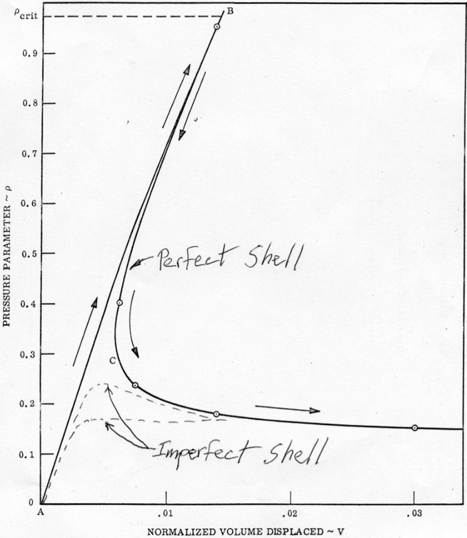
The advantage of curved monocoques is that their buckling loads are much greater than those flat plates. For example, you can safely stand on a soda can even though it is made out of relatively cheap aluminium. However, once the soda can does buckle all hell breaks loose and the whole thing collapses in one big heap. What is more, curved structures are very susceptible to initial imperfections which drastically reduce the load at which buckling occurs. Flick the side of a soda can to initiate a little dent and stand back on the can to feel the difference.
Imperfection sensitivity of a cylinder. The plot shows the drastic reduction in load (vertical axis) that the perfect cylinder can sustain with increasing deformation (horizontal axis) once the buckling point has been passed. This means that an imperfect (real) shell will never reach the maximum load but diverge to the lower load level straight away.
This problem is exacerbated by the fact that the shape of the tiny initial imperfections, typically of the order of the thickness of the shell, can lead to vastly different failure modes. Thus, the behaviour of the shell is emergent of the initial conditions. In this domain of complexity it is very difficult to make precise repeatable predictions of how the structure will behave. For this reason, curved shells are often called the “prima-donna” of structures and we need to be very careful in how we go about designing them.
A rocket is naturally exposed to compressive forces as a result of gravity and inertia while accelerating. In order to increase the critical buckling loads of the cylindrical rocket shell, the skin is stiffened by internal stiffeners. This type of construction is known as semi-monocoque to describe the discrete discontinuities of the internal stiffeners. A rocket cylinder typically has internal stringers running top to bottom and internal hoops running around the circumference of the cylindrical skin.
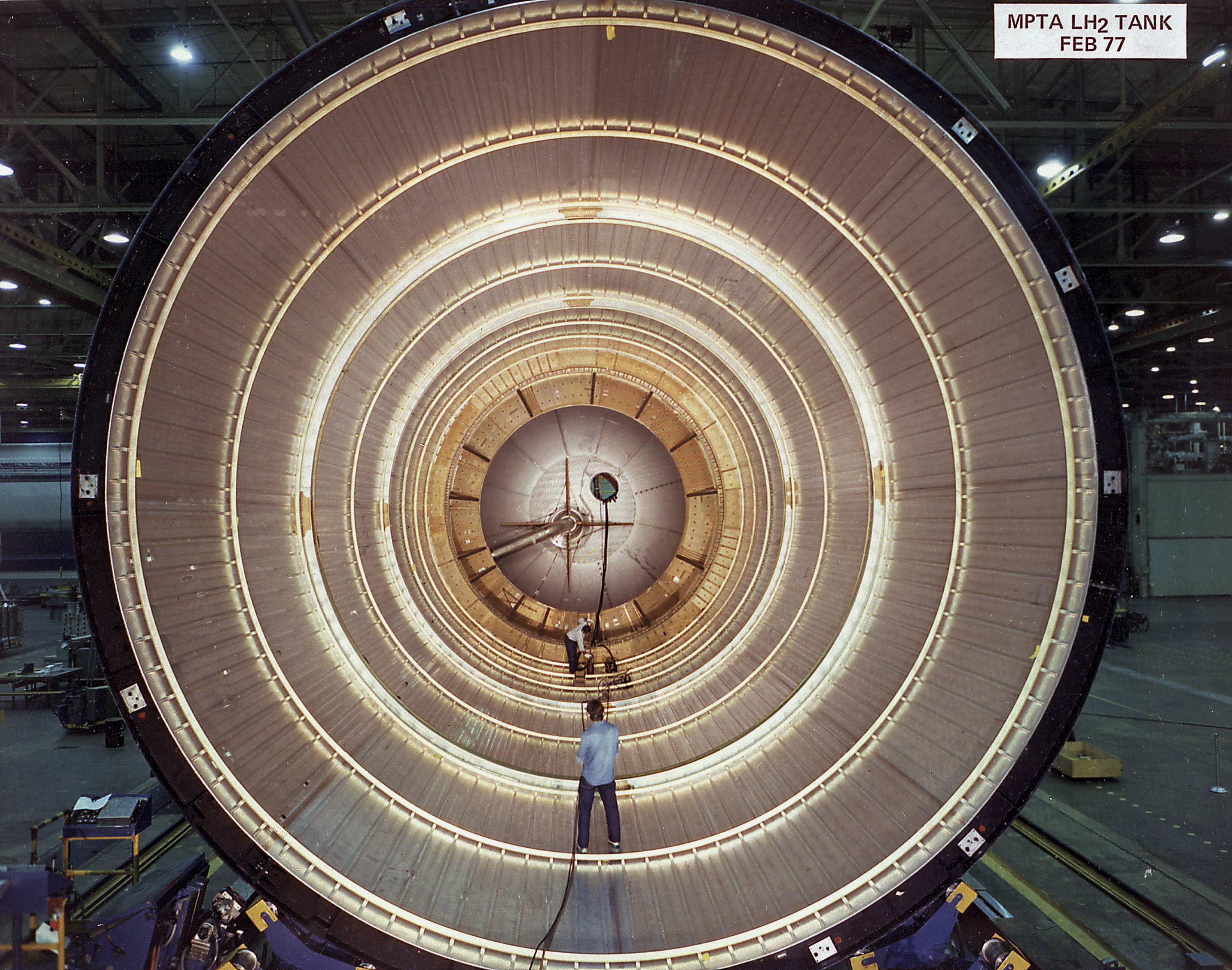
Space Shuttle internal structure of propellant tank. Note the circumferential hoops and longitudinal stringers that help, among other things, to increase the buckling load.
The purpose of these stringers and hoops is twofold:
First, they help to resist compressive loading and therefore remove some of the onus on the thin skin.
Second, they break the thin skin into smaller sections which are much harder to buckle. To convince yourself, find an old out-of-date credit card, cut it in half and repeat the previously described experiment.
The cylindrical rocket shell has a second advantage in that it acts as a pressure vessel to contain the pressurised propellants. The internal pressure of the propellants increases the circumference of the rocket shell, and like blowing up a balloon, imparts tensile stretching deformations into the skin which preempt the compressive gravitational and inertial loads. In fact, this pressure stabilisation effect is so helpful that some old rockets that you see on display in museums, most notoriously the Atlas 2E rocket, need to be pressurised artificially by external air pumps at all times to prevent them from collapsing under their own weight. If you look at the diagram below you can see little diamond-shaped dimples spread all over the skin. These are buckling waveforms.
Atlas 2E Ballistic Missile with buckling “diamonds” along the entire length of the external rocket skin (via Wikimedia Commons)
NASA Langley Research Center has been, and continues to be, a leader in studying the complex failure behaviour of rocket shells. To find out more, check out the video by some of the researchers that I have worked with who are developing new methods of designing the next generation of composite rocket shells.