Earlier this year, I had the privilege of working on a research project at NASA’s Langley Research Centre. Apart from interacting with world-renowned scientists and engineers, what impressed me most was the mind-blowing heritage of the site.
NASA Langley is the birthplace of large-scale, government-funded aeronautical research in the US. It was home to research on WWII planes, supersonic aircraft, the lunar landers and the Space Shuttle. Who knows how the Space Race would have panned out without the engineers at NASA Langley?
NASA Langley was established in 1917 as NACA’s (short for National Advisory Committee for Aeronautics and renamed to NASA in 1958) first field centre and is named after the Wright brothers rival Samuel Pierpont Langley, who’s Aerodrome flyer twice failed to cross the Potomac river in 1903.
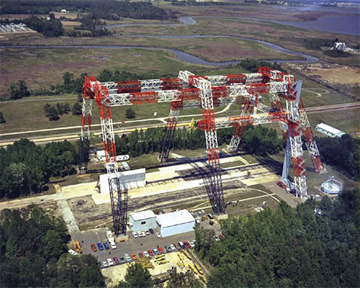
Amid the new composites facilities I was working on are strewn old gems such as NACA wind-tunnels from the 1920s and 1930s, and the massive “Lunar Landing Research Facility”, or simply “The Gantry”, used to test the Apollo lunar landings in the 1960’s. During Project Mercury NASA Langley was the home of the Space Task Group, a team of engineers spearheading NASA’s first human spaceflight between 1958 and 1963. The gantry has since been re-purposed for land-based crash landings, such as on the Orion spacecraft.
NASA Langley Test Gantry [1]Another historic site is the Aircraft Landing Dynamics Facility (ALDF), a train carriage that could be accelerated by 20Gs up to 230 mph by a water-jet spewing out the rear, and used to test impact on landing gears and airfield surfaces. The facility has provided NASA and its partners and invaluable capability to test tires, landing gear and understand the mechanism of runway friction. Prior to WWII many engineers were convinced that the abundance of rivers and sea water would mean that the aircraft would land primarily on water. As a result research on the mechanics of landing on terra firma was lagging behind and post WWII almost a third of all aircraft accidents could be attributed to landing issues [2]. Throughout its 52 years of operation the ALDF has saved thousands of lives by making aircraft safer.
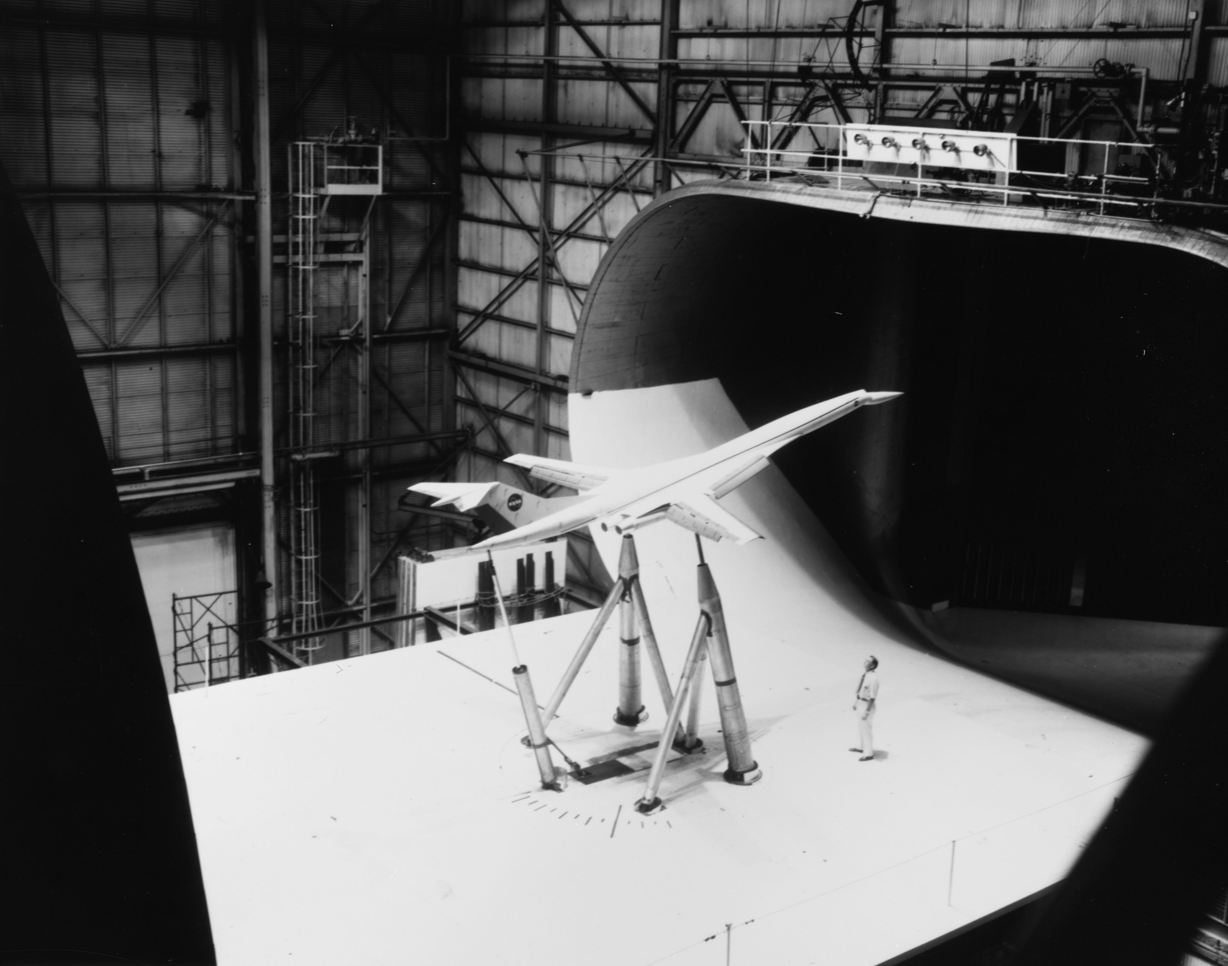
As the centre’s original aim was to explore the field of aeronautics, specifically aerodynamics and propulsion, the world’s largest wind tunnel was constructed at Langley in 1934. At the time the Full-Scale Wind Tunnel was one of the first to fit an entire full-scale aircraft with a whopping 30 by 60 foot cross-section. The tunnel’s 4000 bhp electric motors (4000 bhp !!) accelerated the airflow to 118 mph (181 km/hr) and was used to test basically every WWII aircraft prototype. After the war, both the F-16 and the Space Shuttle were tested in the Full-Scale Wind Tunnel. Even though it was declared a National Historic Landmark in 1985 it was demolished in 2010.
Full Scale Wind Tunnel [3]As rocket research gained importance in the 1940’s the capabilities were extended from subsonic to supersonic and even hypersonic research. Even today the importance of aerodynamics research is obvious as one drives past the 14×22 foot subsonic wind tunnel on the way to the main gate.
The 1930s in the USA were a golden age for aeronautics. Before World War I, the US government and military did not place high priority on aeronautics research. In fact the total research spending between 1908 and 1913 totalled a measly $435,000 compared to a whopping $28 million spent by Germany. Thus put the US behind countries like Brazil, Chile, Bulgaria, Spain and Greece [4].
NASA Langley subsonic wind tunnel on the way to the main gate [5]All of this changed when aeronautical research started to kick-off at NACA, specifically at Langley Research Center. In the 1930’s aerodynamicist Eastman Jacobs developed a systematic way of designing airfoil shapes, and to this day standard wing shapes are designated with a NACA identification number.
During the 1930s various airshows and flying competitions in Europe sparked competition to design the fastest aircraft. For example, the Schneider Trophy was an annual competition for seaplanes and was won on three occasions by Supermarine aircraft designed by Reginald J. Mitchell, who later used the insights gained from these competitions to design the iconic WWII fighter Supermarine Spitfire. However, at some point the speed records hit a wall just shy of the speed of sound and it was unclear if it was possible to break the “Sound Barrier” at all.
Researchers were having a tough time figuring out why drag increased and lift decreased as an aircraft approached the speed of sound. It was not until 1934 that a young Langley researcher John Stack captured the culprit on a photograph of a high-speed wind tunnel test of an airfoil.
As the aircraft airspeed approaches the speed of sound, small pockets of supersonic flow develop on the suction surface of the airfoil as the airflow accelerates over the curved profile. For thermodynamic reasons these pockets of supersonic flow terminate in normal shock waves and the ensuing increase in pressure exacerbates the adverse pressure gradient on the suction surface. Ultimately, this leads to premature boundary layer separation and thereby decreases lift and increases drag (see figure below). John Stack was the first person to capture this phenomenon on film and paved the way for supersonic flight in the years to come.
Transonic shock wave [6]Other major accomplishments of NASA Langley Research Center include:
The idea of designing specific research aircraft dedicated to supersonic flight, which led to the world’s first transonic wind tunnel
Simulation and testing of landing in lunar gravity using the Lunar Landing Facility
The Viking program for Mars exploration
5 Collier trophies, the U.S. aviation’s more prestigious award, including the 1946 trophy to Lewis A. Rodert, Lawrence D. Bell and a certain Chuck Yeager for the development of a wing deicing system. Fred Welck won the trophy in 1929 for the NACA cowling, an engine cover for drag reduction and improved engine cooling
The grooving of aircraft runways to improve the grip of aircraft tires by reducing aquaplaning, now an international standard for all runways around the world.
Grooved airport runway [7]On March 3rd the NASA reached a major milestone by celebrating its centennial. Since 1917 Langley Research Center has played an important role in the successes of American and international air and space travel. In recent years the media has focused mostly on new commercial space companies such as Orbital Sciences and Space-X.
But as Elon Musk rightly points out, Space X’s exploits would not be possible without NASA’s achievements throughout the last 100 years and its continuing support of the private sector. In fact, NASA made one of it’s first steps into public-private partnerships as early as the 1940’s with the development of the Bell X-1, the first manned aircraft to break the sound barrier.
In that respect join me in congratulating NASA to its centennial and to more exciting aerospace developments for the next 100 years!
References
[1] “Nasa langley test gantry” by Unknown – NASA. Licensed under Public Domain via Wikimedia Commons – https://commons.wikimedia.org/wiki/File:Nasa_langley_test_gantry.jpg#/media/File:Nasa_langley_test_gantry.jpg
[3] “Full Scale Wind Tunnel (NASA Langley)” by Photocopy of photograph (original in the Langley Research Center Archives, Hampton, VA [LaRC]) (L73-5028). Licensed under Public Domain via Wikimedia Commons – https://commons.wikimedia.org/wiki/File:Full_Scale_Wind_Tunnel_(NASA_Langley).jpg#/media/File:Full_Scale_Wind_Tunnel_(NASA_Langley).jpg
[5] “14×22 Subsonic Tunnel NASA Langley” by Erik Axdahl Axda0002. Licensed under CC BY-SA 2.5 via Wikimedia Commons – https://commons.wikimedia.org/wiki/File:14x22_Subsonic_Tunnel_NASA_Langley.jpg#/media/File:14x22_Subsonic_Tunnel_NASA_Langley.jpg
[6] “Transonic flow patterns” by U.S. Federal Aviation Administration – Airplane Flying Handbook. U.S. Government Printing Office, Washington D.C.: U.S. Federal Aviation Administration, p. 15-7. FAA-8083-3A.. Licensed under Public Domain via Wikimedia Commons – https://commons.wikimedia.org/wiki/File:Transonic_flow_patterns.svg#/media/File:Transonic_flow_patterns.svg
[7] “Pista Congonhas03” by Valter Campanato/ABr – Agência Brasil. Licensed under CC BY 3.0 br via Wikimedia Commons – https://commons.wikimedia.org/wiki/File:Pista_Congonhas03.jpg#/media/File:Pista_Congonhas03.jpg
I have just returned from the International Conference for Composite Materials (ICCM) in Montreal, Canada and would like to share a few observations and key points about the developments in the composite world that may not be so easily accessible to a broader audience.
1) The Great Advance – Applications
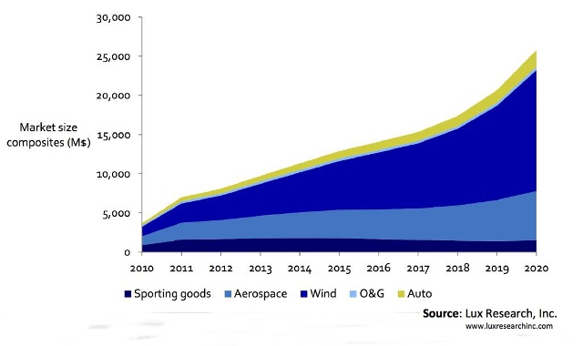
ICCM is the biggest conference for composite materials and this year united over 1500 delegates from academia and different industrial representatives from the classical sectors aerospace, wind energy and high performance cars to newer sectors such as mass market cars (e.g. BMW i3), biomedical applications and even musical instruments. The motto of the conference “Composite Materials: The Great Advance” aptly captures the current state of technology in the industry. Since the 1960 considerable amount of research has been conducted to elucidate the mechanical and chemical properties of the fibre material, matrix and cured composite under various conditions such that the global behaviour of these materials is now sufficiently characterised. This maturity in technology coupled with the ever decreasing costs and the inherent benefits of high specific stiffness and strength that fibre-reinforced plastics have to offer, has led to the increasing application of composite materials in very different industries that we see today. Thus the “great advance” of composite materials towards wide-spread use in many industrial sectors.
Fig. 1. Composite materials growth broken down by sectors (1)
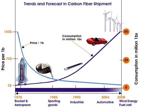
Fig. 2. Carbon Fibre Market (2)
2) The Great Advance – Novel Technologies
Furthermore, “The Great Advance” also relates to novel composite materials with much greater complexity that blur the lines between what is a material and what is a structure. Of course on a macroscopic scale one could say the steel in a steel bridge is the “material” that has been used to construct the “structure” that is the bridge. Therefore in this classical interpretation steel is just the building block to make the bridge, while the structure itself is the final product that performs a function. However on a microscopic scale we could argue that steel is a structure in itself since it is “constructed” of different sized grains that contain different metallic compounds and is thus an arrangement of small particles i.e. a microstructure. We could of course continue this argument further and further up to the atomic scale at which point we have reached the field of nanotechnology. This field of research has enjoyed much popularity in recent years since by manufacturing our products from the ground-up, i.e. from the nanoscale to the macroscale, we can control the properties of our product at multiple length-scales and therefore tailor the characteristics to be optimal for the desired function in service or even add some sort of multi-functionality to the structure/material. Since the material and structure are built at the same time the dividing line that used to distinguish between these two concepts is blurred. Even for a simple composite laminate comprised of a stack of individual layers this divide is no longer so clear since we can define the properties of each ply in the stacking direction and therefore have control over one more length scale.
Therefore in the future there will be a great advance towards novel and multifunctional materials/structures that perform so much more than carrying structural loads. Currently the design of composite structures is still in some cases dominated by a “black aluminium” approach. That is taking the current designs that have worked so well over the last decades using aluminium and replacing them by an equivalent composite design. The problem with this is that on one hand the composite material may not be suitable to carry loads in the same configuration e.g. loads through the thickness have to be avoided to prevent delaminations. Most importantly however, such a design approach hinders the greatest advantage of this new material system, which is to facilitate entirely new structures in terms of functionality and shape that arise as a results of their inherent properties. Only by completely re-designing structures from the ground-up and taking the intricacies of this new material system into consideration can we arrive a new optimal solutions or conversely ascertain that a metal solution actually works better under some circumstances. In the following I want to share a few exciting technologies that you may see in the near future.
1) Variable stiffness technology
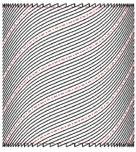
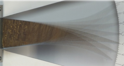
This is my field of research and essentially what we are currently doing is changing the fibre direction over the planform of the plate such that we have curvilinear fibres rather than the straight fibre laminates that we use today. In many aerospace applications we require different laminate stacking sequences in different parts of the structure. Abruptly changing from one stacking sequence to another can lead to stress concentrations and thus structurally weaker areas at the interface. Using the variable fibre concept we can easily spatially blend from one layup to another to reduce these problems. Furthermore, we can arrange the fibre paths to follow the dominant load paths as for example around a window in an aircraft fuselage. Loads in a structure always follow the path of highest stiffness. So by aligning the fibres in the load direction in supported areas of the laminate (for example the vertical edges in Fig. 3 below if the load is applied vertically onto the horizontal edges), a large portion of the stress can be removed from the unsupported centre of the panel, which can greatly improve the elastic stability of the structure. This has great potential for future wing structures since the design of wing skins is greatly governed by local buckling (Fig. 4). It has been shown that the buckling loads can be improved by 70%-100% using variable stiffness technology (5), thus the possibility exists to reduce the weight of wing structures by up to 20% using this technology.
Fig. 3. A variable angle tow laminates (3)
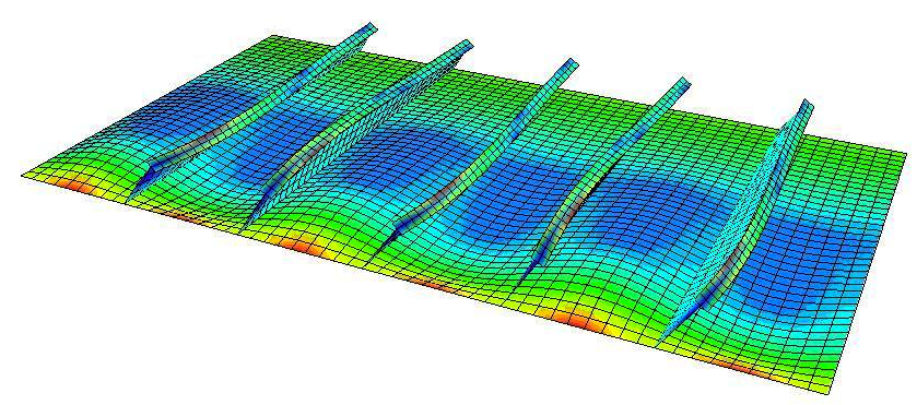
Fig. 4. Buckling analysis of a stiffened wing panel. The stiffeners break the buckling mode shapes into smaller wavelengths that require higher energy to form than a single wave (4)
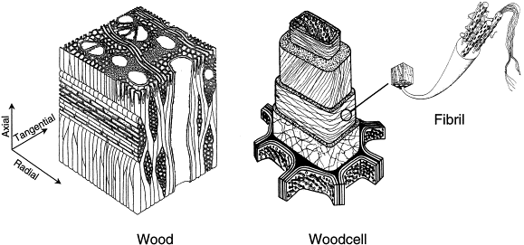
Another form of various stiffness technology is placing material in areas where it is needed and removing it from areas where it is not required. Nature is an expert in achieving this and many of our current design are based on bio-mimicry. For example, your bones are continuously being re-modelled based on the stresses that are placed on your skeleton. In this way the density of your bones is increased in highly-stresses areas and decreased in areas that are not used so much. In the same way sea-sponge arranges its structure in a way to achieve the most efficient design. Similarly, wood possesses an incredibly complex microstructure that is composed of different structural hierarchies at different length scales. This is similar to a rope where individual fibres are twisted together to make strands, strands are twisted together to make bundles, and bundles twisted together to make the complete rope. This approach of designing at multiple length-scales makes wood very ductile and resilient to cracks. In this manner attempts have been made to reproduce such a hierarchical design by arranging short fibres using standing ultrasonic waves.
Fig. 5. Microstructure of wood. Notice the different structures at different length scales that gives wood its inherent strength (6).
2) Self Healing
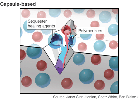
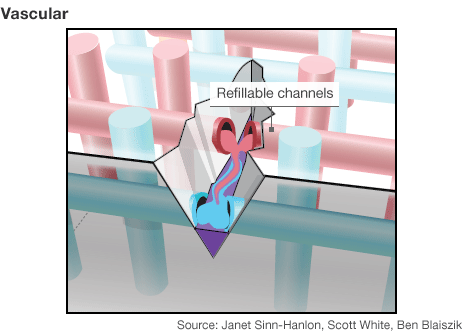
Yes, materials can heal themselves. The most popular example is that of self-healing asphalt, which was presented a few years ago at a TED conference. In terms of composites 100% recuperation of mechanical properties have been achieved when the mode of failure has been dominated by matrix cracks. In high performance composites the matrix is currently some sort of thermoset or thermoplastic, which allows vascules of uncured resin to be included in the structure which may break open as a crack propagates. The uncured resin then permeates through the open crack and cures in-situ to repair the full functionality of the part. The dissemination of the healing process can also be achieved using very thin vascules that are arranged throughout the part. In this manner the structure starts to behave very much like a living organisms with the vascules serving as pathways for repair very similar to the veins in an organism. Recently, a great article by the BBC summarised the major achievements in this field.
Fig. 6. Self healing capsules (7)
Fig. 7. Self healing vascules (7)
3) Nanotechnology
Nanotechnology has been extremely popular during the last 20 years due to the fact that theoretical predictions promise incredible benefits for almost all applications in engineering. In terms of advanced composites however, there are still problems of evenly dispersing nanotubes in resins with agglomeration or alternatively producing continuous nano-strands at low costs. In the aerospace industry they show great promise in increasing the electrical conductivity of laminates to improve their resistance against lightning-strike, creating structures for magnetic shielding and providing interlaminar strengthening using nano-forests. One of the cooler things I saw at ICCM was research conducted on nano-muscles, which are essentially nano-fibres that have been twisted into a rope and can achieve very high actuation forces and strokes at very little mass.
4) Structural Batteries / Energy Harvesting
Solar power has incredible potential as an energy source since it is the largest form of energy available for consumption on earth and is limitless. However, solar power is sporadically dependent on the weather conditions, which makes energy conversion rather cost intensive and inefficient. However, solar energy harvesting might find increasing use if actively integrated into load-bearing components as a multi-functional structure. Bonding thin-film solar cells onto lightweight composites would eliminate the material redundancy of stand-alone supporting structures and could easily be integrated into current laminate manufacturing technology. Photovoltaic (PV) cells have been embedded in composite laminates and their performance has not been impeded by the curing process. However, the performance of the PV cells diminishes rapidly under static loading since the loading causes cracks in the cells. Similarly there are ideas to create structural batteries such that the load carrying chassis of a car can be “charged-up” to additionally serve as the battery for an electric powertrain. Of course this would have the great advantage that the heavy batteries used today could be eliminated to some extent. BAE systems are working on technology to embed battery chemistries into the carbon fibre fabric.
5) Morphing
Finally, morphing or shape-changing structures have been extensively studied since the 1970’s for providing aircraft with the possibility of adapting the shape of their wings to provide the optimal lift for different flight scenarios. Of course this is to some extent already used in aircraft with the aid of leading edge slats and trailing-edge flaps to increase the lift-coefficient for slower flight regimes such as landing and lift-off and in Formula 1 using drag reduction system of the rear wing. However, slats and flaps on an aircraft greatly increase the drag of the profile during deployment and increase the weight of the structure do the heavy actuation mechanism. Therefore the aim is to design an integral system such as the trailing-edge design shown below. Other examples of morphing structures include air intakes for cars, noise-reducing chevrons on jet-engines, or high-temperature composites used for jet-engine turbine blades that change there angle of attack based on the temperature of the airflow around them.
Fig. 8. A morphing trailing edge using a flexible honeycomb (8).
However, in most cases these technologies are very difficult to apply to primary aircraft structures. This is because there is a direct conflict between the high-stiffness, high-strength requirement for carrying loads and the low-stiffness, large-deflections required for shape-changes. Thus, a driver to facilitate these technologies will be the development of materials that change there mechanical properties under different circumstances.
3) The Great Advance – Solving “big” problems for larger scale implementation
Finally, one of themes during the conference was trying to solve some of the major problems faced by the industry hindering further implementation of current composite technology in all industrial sectors. Of course for some industries such as mass consumer automobiles the biggest barrier to entry is cost. The new BMW i3, which will enter the marketplace at the start of 2014, will cost £30,000+ and is therefore quite a big investment for a small city vehicle. Of course some of the cost can be attributed to the cost of the electrical drivetrain and batteries but other manufacturers such as Renault have shown that a lot of these costs can be reduced by employing a scheme based on renting batteries rather than buying them with the vehicle. In case of the i3 a lot of the extra cost is simply down to the fact that BMW are the first to build a mass produced automobile using a large amount of fibre-reinforced plastics in primary structural parts. Not only is cost of raw material much higher than for lightweight metals such as aluminium but the manufacturing processes and supply chain management required for reliable mass production were simply not in-place beforehand. Furthermore, a shift in design methodologies is required since the chemical and mechanical behaviour of composites is so different from the metal environment that the automobile industry is so used to dealing with. As an example, proving the structural integrity for the incredible rigorous crash/impact certification using rather brittle composite materials compared to more ductile metals is a challenge in itself. Thus, the relatively high price-tag of the i3 incorporates some of the research and development costs that BMW have had to face in developing composite technology for their market sector. No doubt the cost of mass market composite cars will reduce drastically in the next decade as the raw material price further reduces and design methodologies and manufacturing processes mature.
Another major issue hindering the implementation of composites especially in the aerospace industry is the difficulty of predicting the failure behaviour of these materials. On problem is the large number of failure modes that may occur: fibre breakage, matrix cracks, delamination, fibre crimping, fibre-matrix debonding, global and local buckling etc. and thus finding accurate failure loads for all these phenomena under different load cases. Since a larger number of these failure mechanisms originate on a local, micro-mechanical scale high-fidelity 3D Finite Element models are often needed to fully understand the mechanisms of failure and predict the load-carrying capability of different structures. Considering the size of any commercial aircraft it is absolutely inconceivable to apply such detailed and computationally expensive analysis tools to every part of an aircraft. Furthermore, the failure mechanisms are not as well defined as for metal materials. That is in classical tensile or compressive tests a specimen may undergo some form of non-linearity that may for a metal specimen be classified as a failure event but for the composite considerable residual strength is available. Conversely the failure behaviour of composites can be very brittle with very little warning compared to the gradual, ductile failure mechanism of most metals used in the aerospace industry. Considering the intricacies of composite failure modes and the fact that the individual failure modes may interact or even change in criticality depending on the size of the component and environment in which it is used, it is no wonder that currently very conservative safety factors are being employed for primary composite aircraft structures that greatly offset the weight-savings that are possible using this new material system. Thus, one of the biggest if not the biggest topic in composite structural design for the next couple of years will be the challenge of developing simple and yet robust failure criteria to be used for composite designers.
(5) Gürdal Z, Tatting B, Wu C. (2008). “Variable stiffness composite panels: Effects of stiffness variation on the in-plane and buckling response”. Composites: Part A, 39(5), pp. 911-922.
(6) Greil P, Lifka T, Kaindl, A. (1998). “Biomorphic Cellular Silicon Carbide Ceramics from Wood: I. Processing and Microstructure”. Journal of European Ceramic Society, 18(14), pp. 1961-1973.
(7) Rincon, P. (2012). “Time to heal: The material that heal themselves.”http://www.bbc.co.uk/news/science-environment-19781862
(8) Daynes S & Weaver P.M. (2011). “A Morphing Wind Turbine Blade Control Surface”. Proceedings of the ASME 2011 Conference on Smart Materials, Adaptive Structures and Intelligent Systems. Phoenix, AZ: ASME.

![NASA Langley subsonic wind tunnel [2]](https://rgroh.com/wp-content/uploads/2015/05/14x22_Subsonic_Tunnel_NASA_Langley.jpg)
![Transonic shock wave [4]](https://rgroh.com/wp-content/uploads/2015/05/Transonic_flow_patterns.svg_.png)
![Grooved airport runway [3]](https://rgroh.com/wp-content/uploads/2015/05/Pista_Congonhas03.jpg)