In this episode I am speaking to Aaron Daniel and Peter Shpik of Alpine Advanced Materials. Alpine Advanced Materials specialises in the design and manufacture of custom-engineered parts and products for demanding aerospace and energy applications. The company is currently commercialising a high-performance material known as HX5™, which is a thermoplastic nanocomposite originally developed by Lockheed Martin Skunk Works® over a decade of testing and validation.
HX5™ was originally developed to replace aluminum at half the weight but with the same strength and stiffness. On top of that HX5™ has excellent durability in harsh environments such as in outer space, in radioactive settings or around aggressive chemicals. As a result, this new nanocomposite material is already being used on jet fighters, high-speed helicopters, UAVs, rockets, and satellites. In this episode of the aerospace engineering podcast Aaron, Peter and I talk about:
the importance of lightweighting in the aerospace industry
Throughout the last four decades the exploitation of fibre-reinforced plastics (FRP) in engineering structures has been steadily diversifying from sports equipment and high performance racing cars, to helicopters and most recently commercial aeroplanes. Composite materials are essentially a combination of two or more dissimilar materials that are used together in order to combine best properties, or impart a new set of characteristics that neither of the constituent materials could achieve on their own. Engineering composites are typically built-up from individual plies that take the form of continuous, straight fibres (eg. carbon, glass, aramid etc.) embedded in a host polymer matrix (eg. phenolic, polyester, epoxy etc.), which are laminated layer-by-layer in order to built up the final material/structure.
All manufacturing processes are subject to a certain degree of variability. Composite materials differ from most metallic manufacturing routes in that the material is generated at the same time as the structural geometry of the part. In the aerospace industry autoclave components of pre-impregnated reinforcements are the dominant mouldings being used. In this case the hardest variable to control is the thickness dimension and this will be the major concern of this article.
Lean manufacturing calls for variability on thickness expressed as a standard deviation of 1/6th the drawing tolerance – the “6-Sigma” tolerance band – giving a thickness defect rate of 1 in 1,000,000. In reality current thickness defect rates are in the range of 1 in 10 for composite components (1). The biggest influence on laminate thickness is the consolidation pressure. As the consolidation pressure is increased the laminate is compacted more and thus more resin may be bled out of the prepreg. As a result the volume fraction of fiber can vary from just around 50% at 1 bar consolidation to almost 70% at 6 bar. Such large variations in volume fraction will naturally influence the consolidation thickness. The external pressure “felt” by the laminate is not just a function of the target autoclave setting. Insufficient contact between the vacuum bag and the laminate and wrinkles in the bag will greatly reduce the consolidation pressure experienced by the laminate. Since the vacuum bag application is a manual process and the bagging material can be quite flimsy certain amount of wrinkling is inevitable. Thus it can be very difficult to reduce this type of variability and in the worst-case defects such as delaminated plies may occur.
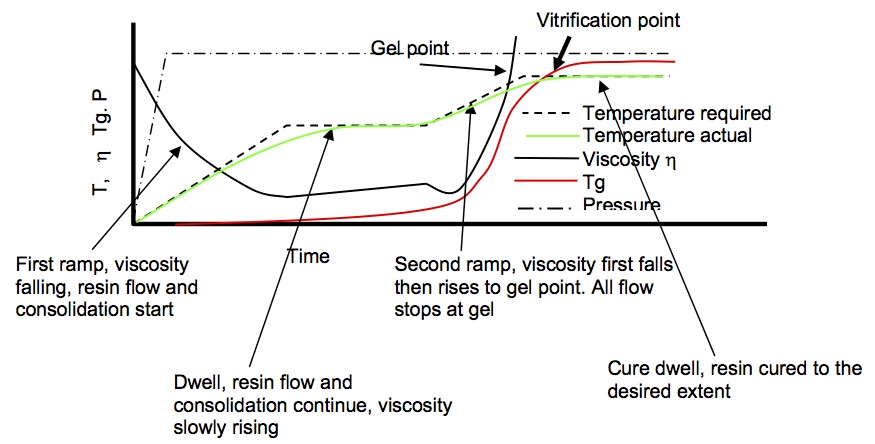
During curing the external temperature is typically ramped up in two stages and held constant in between, the so-called “dwell period”, in order to allow the actual mould temperature to catch-up and ensure full consolidation and cure. During the early parts of the cure the resin viscosity will first reduce as a result of the increasing temperature but then increase suddenly as the mould temperature reaches the gelation point and thus causes the resin to solidify. When the resin viscosity is low internal flows of resin will occur.
Composite Consolidation Programme: Variation of Viscosity with Temperature (3)
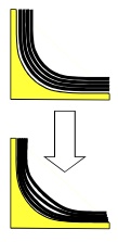
Around corners the difficulty of preventing fibre wrinkling or fibre bridging is added. If plies cannot slip over each other as they consolidate over inside radii, fibre bridging will occur and the laminate will get thicker in the corner. The fibres that bridge the radius will directly react the consolidation pressure leading to a reduced resin pressure beneath the bridged fibres. Resin will, therefore, tend to flow towards this region of bridged fibres but if this does not sufficiently occur high local voidage will result.
Fibre Bridging (3)
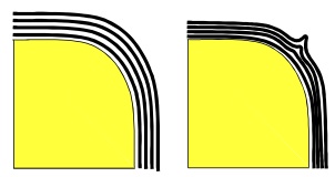
Fibre Wrinkling (3)
Upon consolidation the resin will start to shrink and since it is constrained, the bridged pocket will be exerted under tensile stress. This may cause cracking in the brittle resin and thus cause internal failure before any external load has been applied on the part. Fibre bridging may be reduced by using rollers to press the fabric into the corner or by incorporating slip-lines into the layup. However, especially in the latter case this will complicate the layup and increase manufacturing times.
Slip Lines in Layup (3)
Equally, if plies cannot slip over external radii then fibre wrinkling or “earing” will occur. Although this will not produce a resin sink the wrinkled area will be voidy and have poorly controlled fibre orientation leading to a reduction in mechanical properties. Fibre wrinkling may also be exacerbated by wrinkles in the vacuum bag over the corner.
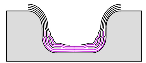
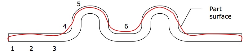
Taking the example of the component below the real laminate thickness and target thickness can be widely different. In zone 1 the laminate is likely to be thinner as a result of resin bleeding out of the component unless some sort of resin dam is used. Zones 3 and 5 are likely to be thinner due to resin flow from these areas into the resin sink over the internal radii at zone 4. Ideally the effects of internal and external radii would cancel out at zones 4 and 5 but inaccuracies in the layup or induced tensions in the plies will typically mitigate this. The most critical section of the component is undoubtedly zone 6, where high voidage is very likely due to the difficulty of bleeding sufficient resin into the area and the two adjacent internal radii.
Thickness Variation in Composite Moulding (3)
Thickness deviations are only one form of variability. Other defects may stem from part design, manufacturing design, the lay-up process or the autoclave process. To produce reliable components with tightly toleranced dimensions lay-ups are typically made balanced (equal number of ±Angle° plies) and symmetric about the mid-plane in order to avoid thermally induced distortions. Unbalanced or unsymmetric laminates manufactured as plates on flat tools will warp and twist as a result of the different thermal expansion coefficients of different layers. However, if the resin content varies between different plies the thermal properties will naturally vary and the laminate will be unbalanced. For a typical pre-preg the weight/unit area tolerance limits can be up to 5% on both pre-preg and fibre weight, and resin contents may even have a slightly wider tolerance band (1). Considering that resin and fibre contents directly influence the mechanical properties of the composite it can be quite challenging to decrease variability and guarantee reliable components with such a wide tolerance band.
Additional distortions arise if aluminium or steel tooling is used. Metal tools have higher coefficients of thermal expansion than composites and cure in the autoclave can occur at elevated temperatures of typically 180°C. Therefore the tooling will expand more than the composite, putting strains onto the outermost ply. These surface strains may be exacerbated by local features such as a corners and joggles.
A considerable amount of variability around corners is the so-called “spring-in” effect. As the laminate cools down from cure it will contract far more through the thickness than in plane. In order to maintain continuity of the profile without causing residual stresses the corner angles will close up. This can result in changes of corner angle of about 1° for 150°C change in temperature. Other defects such as fibre wrinkling or bridging will worsen this effect. In general it is very difficult to accurately predict what will happen for certain geometries.
Composite Spring-In (3)
In addition, other sources of defects include:
Surface scratches, depressions and dents
Delaminations between plies or voids
Material inclusion within the layup such as a ruler
Undercure or overcure (burning)
Tool drop or other impact events that can cause internal resin damage or delaminations
In general most of these defects can be controlled by well-trained and highly motivated factory staff. Engineers and factory management should work together to ensure that all employees involved with the layup and curing process are aware of all possible sources of variability and how to mitigate these. In this respect detailed technical training entrusts more responsibility on the shoulders of employees and gives the staff the deserved recognition of being an important cog in the works of the company. Furthermore, the importance of a well-lit, comfortable working environment and positive atmosphere should not be understated and can go a long way to guaranteeing high-quality mouldings. A well-trained, highly motivated and happy staff is the first line of defence against poor parts.
Next it is important to follow a concurrent design philosophy throughout the development process of a component. Thus the design, stress, manufacturing and quality control engineers must simultaneously work together in order to come up with a solution that fulfils all functional needs but can also be manufactured to a profit without unnecessary defects. The classical philosophy of separately designing a functional component, which is handed to the production engineers, makes manufacturing high-quality laminates incredibly difficult and will incur significant secondary costs.
Finally, specific details of possible sources of variability can then be handled on a case-by-case basis. Thus the component’s shape and type of prepreg to be used will influence the mould material shape design; curing temperature and pressure; possible inclusion of slip lines and laminate stacking sequence as discussed above. In conclusion, manufacturing high-quality laminates for the aerospace industry is not an easy task and is even more daunting considering the size of the current all composite Boeing 787 Dreamliner and Airbus A350 XWB projects. Each design decision must be weighed against the influence on manufacturing process and every little detail is important!
References
(1) Potter, Kevin (1996). An Introduction to Composite Products: Design, Development and Manufacture. Springer, 5th Ed. Chapman & Hall, London.
The exploitation of conventional, continuous fibre-reinforced plastics in engineering structures has been steadily diversifying from sports equipment and high performance racing cars, to helicopters and most recently commercial aeroplanes. The main benefits of composite materials, such as their excellent specific strength and stiffness properties, must be viewed with respect to in-plane fibre-direction applications. However, if a composite plate is subjected to significant out-of-plane stresses subsurface delaminations may develop between layers due to the weak through-thickness cohesive strength of the composite (2). Previously, techniques such as Z – pinning, stitching and 3D – braiding have been investigated to improve through-thickness properties but these tend to reduce the in-plane performance of the laminate by damaging primary fibres and inducing fibre waviness (1).
Carbon Nanotube interfacial strengthening
Throughout the last decade the huge interest in Carbon Nanotubes (CNT) has been fuel by their extraordinary intrinsic mechanical, electrical and thermal properties, which make them ideal candidates for multifunctional structures (3). To overcome the weakness of interlaminar strength considerable research has been conducted to develop hierarchical composite structures by using nanoscale CNT reinforcement alongside microscale carbon and glass fibers. Examples in nature such as cell walls and animal shells show that excellent mechanical properties can be obtained from spreading reinforcement over a number of length scales, even if the original constituents are fairly weak (4). This paper reviews the progress in developing such hierarchical composites to improve delamination resistance and through-thickness properties by intra- and interlaminar reinforcement of multiwall carbon nanotubes (MWCNT).
In an attempt to improve the through-thickness properties the introduction of CNTs should,
Ideally be attached radial to the primary fibres and extend into the surrounding matrix to stiffen the fibre/matrix interface, improve the primary fibre surface area and facilitate mechanical interlocking, all of which improves stress transfer.
Result in a uniform distribution of CNTs.
Not reduce the in-plane laminate properties.
Not introduce other secondary or additional modes of failure by damaging the primary fibres.
Allow a scalable, straightforward processing technique that can be easily incorporated with conventional manufacturing processes such as VARTM or pre-preg.
In the literature there are currently two popular methods to achieve this,
Dispersing CNTs in a polymer matrix followed by infusion of pre-forms with the CNT-reinforced resin,
A direct attachment of CNTs onto the external surface of the primary fibres subsequently infused with a pristine resin.
In the following sections the details of the two manufacturing approaches (shown schematically in Figure 1) are outlined and the implications of each approach on through-thickness performance such as interlaminar shear strength, and Mode I and Mode II critical fracture energy discussed.
Fig. 1. Schematic diagram of conventional CFRP and hierarchical CFRP with CNTs in matrix and grown on fibres (4).
CNT-reinforced Matrix
The simplest method to manufacture hierarchical nanocomposites is by mechanically or ultrasonically shear-mixing CNTs into low-viscosity thermosetting resins, and then infusing or impregnating the primary fibre stack using conventional techniques such as VARTM (5; 6; 7). To date the most uniform dispersion of MWCNTs throughout the matrix have been achieved by shear mixing using a three-roll mill (8; 9). On the other hand this approach is limited to short CNTs < 1 mm at low volume fractions of 1 – 2%, which greatly limits the reinforcement potential. Higher volume fractions are to date not possible since the viscosity of the matrix increases rapidly with CNT content leading to incomplete infusion (10) or CNT agglomeration/depletion in different areas of the fabric (11).
Flexural tests of hierarchical composites with glass and carbon primary fibres show that the in-plane stiffness and strength are not impaired by the MWCNTs (5; 8). Qiu et al. (5) actually showed an improvement in tensile strength and stiffness of a glass-fibre composite of 15.9% and 27.2% respectively, while Veedu et al. (12) showed improvements of 142% and 5% for carbon composites. Most importantly, as tabulated in Table 1 short beam shear (SBS) and compression shear tests (CST) have shown increases in the matrix-dominated interlaminar shear strength (ILSS) between 8% and 33%. Scanning electron microscopy (SEM) images show that the MWCNTs in the resin lead to better fibre-to-matrix adhesion as well as pullout and rupture of the MWCNTs before final matrix failure, which consumes additional fracture energy (Figure 2).
Fig. 2. SEM images showing much more matrix stuck to the fracture surface of CNT reinforced matrix suggesting better matrix/fibre adhesion (7)
The SEM images also indicate that the alignment of the CNTs is heavily influenced by the direction of the resin flow during infusion and local orientation of the primary fibres (4). As resin infusion generally occurs in the through-thickness direction the VARTM approach can give some control in aligning the CNTs in the preferred direction for improving transverse properties, although a certain degree of random alignment remains. Furthermore, one study has shown (5) that functionalised MWCNTs resulted in slightly higher SBS shear modulus and strength (~3%) compared to a pristine un-functionalised MWCNTs. Using SEM imagery the authors showed that this stemmed from a superior interfacial bonding between the CNTs and the matrix.
Delamination resistance is generally investigated using Mode – I double cantilever beam (DCB) tests and Mode – II end-notched flexure (ENF) tests. Table 1 summarises the significant improvements of up to 98% and 75% for Mode I and Mode II fracture toughness respectively compared to non-hierarchical composites. The characterisation of the fracture surfaces using SEM imagery has shown that the additional pullout and bridging of the CNT is responsible for the toughening. Similarly, Garcia et al. (13) have developed an efficient technique of growing CNT mats on growth substrates and then “transfer printing” the CNT mats in between tacky pre-preg plies using a roller. Since this process better controls the CNT alignment in the through-thickness direction much higher improvements of fracture toughness of 152% in Mode I and 214% in Mode II were observed. However, the process of “transfer printing” CNT films at every ply interface is a very time consuming endeavour and may therefore not be as applicable to scalable industrial integration as the VARTM process.
Table 1. Improvements in ILSS and delamination resistance of CNT-reinforced composites.
Fibre
Matrix
Nanofiller
Nano- Reinforced Region
Test Method
Improve-ment
Ref. And Year
woven glass
VARTM epoxy
1 wt% of pristine and functionalised MWCNT
entire matrix
SBS (ILSS)
7.9%
(5), 2007
woven glass
epoxy
0.5-2 wt% MWCNTs
entire matrix
Compression Shear Test (ILSS)
9.7% (0.5%)
20.5 (1%)
33% (2%)
(14), 2008
carbon
epoxy
5 wt% cup stacked CNTs
entire matrix
DCB (Mode I)
–
ENF (Mode II)
98%
–
30%
(15), 2007
carbon
epoxy
1 wt% MWCNTs
entire matrix
DCB (Mode I)
–
ENF (Mode II)
60%
–
75%
(16), 2009
UD carbon
pre-preg epoxy
~1% CNT forests
layer between pre-preg plies
DCB (Mode I)
–
ENF (Mode II)
152%
–
214%
(13), 2008
The fabrication of hierarchical composites by impregnating microscale primary fibres with nanoscale-modified resins is limited to maintaining low matrix viscosities. Furthermore, resin flow during impregnation tends to align CNTs parallel to the primary fibre direction, the least desirable orientation for improving through-thickness properties. In this respect growing or “grafting” CNTs directly onto the surfaces of primary fibres followed by infusion with a pristine, low-viscosity matrix allows higher volume fractions and is ideal for orientating fibres radial to the primary fibres. Furthermore, this approach overcomes the problems of CNT agglomeration or self-assembly into bundles as observed when CNT are freely dispersed in a matrix. Three techniques for attaching CNTs onto fibres were found to be most popular in the literature: CNT-modified Fibres
Direct growth of CNTs onto fibres via Chemical or Thermal Vapour Deposition (CVD and TVD) (12)
Electrophoretic deposition (EPD) (6)
Coating of primary fibres with CNT-modified sizing agents (7)
The first example of synthesising CNTs onto carbon fibres via CVD was conducted in 1991 by Downs and Baker (18). In this approach the primary glass or carbon fibres are initially oxidised with nitric acid and the iron catalysts then deposited onto the fibres using incipient wetness techniques such as sputtering, thermal evaporation or electrodeposition (4). The ultimate result is the growth of highly aligned and dense CNT forests onto fibre cloths (Figure 3) that are then stacked and impregnated by infusion techniques such as VARTM (12). Experiments have shown that the CNT forests are efficiently wet-out by liquid resins and polymer melts as a result of capillary forces (6; 19).
Fig. 3. SEM images showing CNT forests (b) grown in woven pristine fibre cloth (a) (12)
Recently, Injection CVD (ICVD) techniques have been favoured to then grow the CNTs on the primary fibres via a pyrolysis of solutions containing a catalyst precursor and a hydrocarbon source (20). The ICVD technique has resulted in better degree of orientation and growth of longer CNTs compared to classical CVD approach.
The most crucial parameters in grafting CNTs onto glass or carbon fibres are,
Choosing a good catalyst for strong anchoring interaction between CNTs and fibres to maximise stress transfer and reduce damage during manufacturing processes,
While
At the same time prevent oxidation damage to the primary fibres by to aggressive a catalyst.
Fig. 4. Electrophoresis (6)
Oxidation and gasification are especially problematic for carbon fibres since the active catalysts deposited onto the fibres etch into the surface and thus may reduce their strength by up to 55% (4). As a solution Bekyarova et al. (6) selectively deposited multi- and single-walled CNTs onto woven carbon fabric using electrophoresis. In this approach MWCNTs are first produced as is using a classical CVD process and then dispersed in an aqueous media between two negative electrodes to charge the CNTs (Figure 4). The dry carbon fabric was then immersed in the CNT doped media and sandwiched between two steel plates connected to a positive charge. Driven by the electric potential, the CNTs are thus deposited onto the carbon cloth and the CNT-carbon fibre performs then infused with epoxy using VARTM. A very simple approach has been presented by Zhu et al. (7) who sprayed nanotubes directly onto woven fibers prior to VARTM processing. The drawback of this technique compared with direct growth methods is relatively little control over the CNT orientation (4).
The pioneering work of Downs and Baker (21) reported a 4.75x increase in interfacial shear strength (IFSS) of a nanofibre-grafted carbon composite, although such incredible improvements have not been repeated thus far. Table 2 summarises interlaminar and delamination resistance enhancements taken from different sources in the literature and based on multiple primary fibre, CNT and matrix combinations. Veedu et al. (12) showed improvements of 348% and 54% for GICand GIIC respectively for MWCNT enhanced SiC woven fabrics using a classical CVD technique; Bekyarova et al. have found improvements of 27% in ILSS for CNT enhanced carbon fabrics using electrophoresis deposition; while Zhu et al. demonstrated improvements of 45% in ILSS of MWNT doped glass fiber reinforced vinyl ester composites using a simple spray up with only 0.015 wt% of CNTs. In all three studies SEM imagery showed that the improvements arise from the increased surface area of the primary fibres and excellent wettability, which facilitates a strong bond between fibres and matrix by mechanical interlocking.
Based on these results the general consensus is that the damage tolerance of a structure can readily be improved by CNT grafting (4). However, there is also a large variability in the results arising from the different manufacturing processes, material combinations and CNT loadings applied that conceal the exact effectiveness of the method. There is agreement that the degree of enhancement is greatly dependent on the orientation and length of the grafted CNTs and further experimental research is required to ascertain the optimal morphology and manufacturing technique to achieve this (4).
Table 2. Improvements in interlaminar strength and delamination resistance for nano-grafted composites.
Fibre
Matrix
Nanofiller
Manufacturing Technique
Test Method
ILSS Improv.
Ref. And Year
woven glass
vinyl ester
0.015% SWCNTs and MWCNTs
Spray-up between plies
SBS
20-45%
(7), 2007
carbon
epoxy
0.25 wt% MWCNTS
Electro-phoresis
SBS
27%
(6), 2006
SiC
epoxy
2 wt% MWCNTs
CVD
DCB (Mode I)
–
ENF (Mode II)
348%
–
54%
(12), 2006
Perspectives
The research so far has focused on demonstrating the great potential of CNTs to improve the through-thickness of properties of conventional FRPs. In the future research should focus on,
Developing scalable manufacturing processes that may find application in real, large-scale industrial applications.
Finding new approaches that solve agglomeration and high viscosity issues to allow higher loadings of CNTs.
Functionalisation of CNTs to improve CNT dispersion and stress transfer with the host matrix.
Reducing or preventing the reduction in strength of primary fibres induced by grafting fibres onto external surface.
Ascertaining the optimal CNT orientation and aspect ratio to optimise the through-thickness performance.
Key References
1. On the effect of stitching on Mode I delamination toughness of laminated composites. Lalit, Jain and Yiu-Wing, Mai. 1994, Composites Science and Technology, Vol. 51, pp. 331-345.
2. One Dimensional Modelling of Failure in Laminated Plates by Delamination Buckling. Chai, Herzl, Babcock, Charles and Knauss, Wolfgang. 11, s.l. : Pergamon Press Ltd., 1981, Int. J. Solids Structures, Vol. 17, pp. 1069-1083.
3. Big returns from small fibers: A review of polymer/carbon nanotube composites. Breuer, O and Sundararaj, Uttandaraman. 6, 2004, Polymer Composites, Vol. 25, pp. 630-645.
4. Carbon nanotube-based hierarchical composites: a review. Qian, Hui, et al. 2010, Journal of Materials Chemistry, Vol. 20, pp. 4751-4762.
5. Carbon nanotube integrated multifunctional multiscale composites. Qiu, Jingjing, et al. 2007, Nanotechnology, Vol. 18, pp. 1-11.
6. Multiscale Carbon Nanotube-Carbon Fiber Reinforcement for Advanced Epoxy Composites. Bekyarova, E., et al. 2007, Langmuir, Vol. 23, pp. 3970-3974.
7. Processing a glass fiber reinforced vinyl ester composite with nanotube enhancement of interlaminar shear strength. Zhu, Jiang, et al. 2007, Composites Science and Technology, Vol. 67, pp. 1509-1517.
8. Thostenson, E.T., Ziaee, S. and Chou, T.W. 2009, Compos. Sci. Techn., Vol. 69, pp. 801-804.
9. Seyhan, A.T., et al. 2007, Eur. Polym. J., Vol. 43, pp. 374-379.
10. Gojny, F.H., et al. 2005, Composites, Part A, Vol. 36, pp. 1525-1535.
11. Fan, Z.H. and Hsiao, K.T., Advani, S.G. 2004, Carbon, Vol. 42, pp. 871-876.
12. Multifunctional composites using reinforced laminae with carbon-nanotube forests. Veedu, Vinod, et al. 2006, Nature, Vol. 5, pp. 457-462.
13. Joining prepreg composite interfaces with aligned carbon nanotubes. Garcia, Enrique, Wardle, Brian and Hart, John. 2008, Composites: Part A, Vol. 39, pp. 1065-1070.
Bibliography (Further Reading)
14. Fan, Z.H., Santare, M.H. and Advani, S.G. 2008, Composites, Part A, Vol. 39, pp. 540-554.
15. Yokozeki, T., et al. Composites, Part A, Vol. 38, pp. 2121-2130.
16. Karapappas, P., et al. 2009, J. Compos. Mater., Vol. 43, pp. 977-985.
17. Godara, A., et al. 2009, Carbon, Vol. 47, pp. 2914-2923.
18. Downs, W.B. and Baker, R.T.K. 1991, Carbon, Vol. 29, pp. 1173-1179.
19. Qian, H., et al. 2010, Compos. Sci. Techn., Vol. 70, pp. 393-399.
20. Mathur, R.B., Chatterjee, S. and Singh, B.P. 2008, Compos. Sci. Techn., Vol. 68, pp. 1608-1615.
21. Downs, W.B. and Baker, R.T.K. 1995, J. Mater. Res., Vol. 10, pp. 625-633.