Tag: Jet Engine

  • Jet Engine Design: Turbine Cooling

    As I described in a previous post, the efficiency of the gas turbine cycle increases as the turbine entry temperature (TET) is increased. Therefore the hotter the combustion gases that enter the first turbine stage the more specific power the jet engine can produce. Of course the TET is bounded by the metallurgical limits of the blade materials, specifically the blade root stress, the creep strain and the melting point of the blade material. The centrifugal stresses at the root increase linearly with the density of the blade material, and linearly with both the square of the rotational speed and the square of the ratio of root-to-tip radius. Creep is the continual and gradual extension of a material under constant load over time. Apart from distorting the physical dimensions and thereby reducing performance of the engine, the induced creep stresses exacerbate the centrifugal operating stresses and will therefore lead to premature failure of the material. A rule of thumb is that the blade life is halved (for a specific blade material and cooling technology) for each 10°C rise in temperature of the metal [1]. The TET has risen from about 1050K in 1944 to about 1750 in the 1994 Rolls-Royce Trent engine. This is partially due to the use of better materials such as Inconel and single-crystal metals with better creep and fatigue properties. However there is a bound to this solution since these nickel-based alloys are typically quite heavy, leading to an increase in centrifugal stresses at the root. Therefore more important in this development has been the technology of channelling  of cold compressor air to cool the turbine blades. Using these advanced cooling techniques has allowed engineers to increase the TET beyond the melting point of the blade materials.

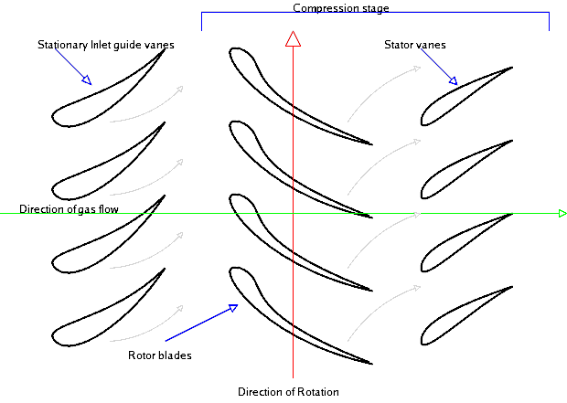
    In a modern engine around 20% of the compressed air is bled off for cooling and sealing purposes for nozzle guide vanes and turbine blades [1]. This internal air system illustrated in Fig. 1 is also used to prevent the any hot mainstream gases from flowing over the heavily stressed blade-attachment discs and control tip clearances between turbine blades and casing. The stators and outer wall of the turbine flow passage use cooling air traveling from the compressor between the combustor and outer engine casing. The turbine rotor blades, disks and inner walls of the turbine flow passage use air bled from the compressor through inner passageways. Since the stators (or nozzle guide vanes) appear before the the first row of rotating blades, the first stage of stators are exposed to the highest temperatures, including local hot-spots from the combustor close by. The temperature at the first rotor stage is then somewhat decreased by dilution of the gases with cooling air, relative velocity effects and power extraction (by gas expansion causing a drop in temperature) from the turbine. In this manner the temperature reduces through each blade row.

    Fig. 1. Detailed turbine cooling paths for stator and rotor stages [2]

     The laws of thermodynamics require that due to combustion inefficiencies there be a pressure loss within the combustor. This means that the mainstream pressure at the first row of stators in the turbine directly after the combustor be lower than at the exit of the final stage of the compressor. It is this pressure difference that we use to drive the cooling air through the internal passageways and into the stators and blades. In this respect improvements in combustor design over the last years has been both an advantage and a disadvantage for cooling engineers. Improvements in combustor design has led to lower pressure losses within the compressor such that more force is available to drive the bled air to the hotter aft parts of the engine. On the other hand, with increasing compression ratios the air within the compressor naturally reaches higher exit temperatures (today around 900K !!! prior to combustion [1]) reducing the effect that the cooling air has on the turbine blades. Furthermore, the cooling air is expensive from an efficiency point of view since work has been done on the compressed fluid and we would ideally like to “waste” as little as possible for secondary cooling purposes. As in most case a compromise has to be struck between power output and turbine life.

    Fig. 2. Evolution of turbine blade cooling technology [3]

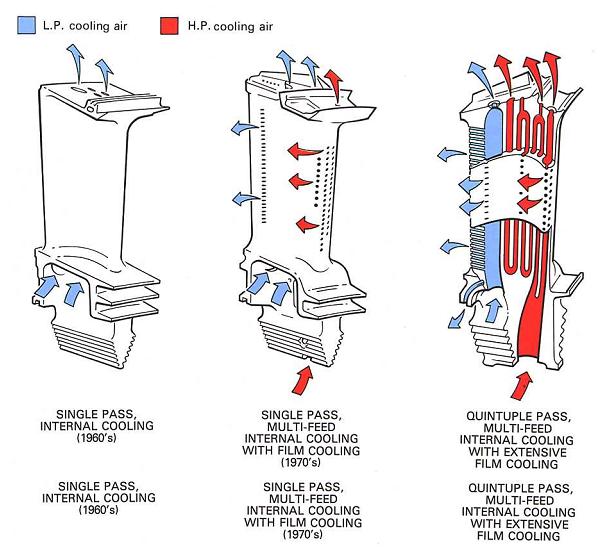
    Figure 2 illustrates the evolution of turbine blade cooling over the last decades. In the early days of the jet era convection cooling was extensively used where the rotating blade acts as a single-pass cross-flow heat exchanger. This means that the bled compressed air flows radially through cooling passages in one-direction from root to tip, driven by the pressure differences and centrifugal forces, thereby removing heat convected to the blade from mainstream gases from axially. Improvements in modern manufacturing technology means that it is now possible to create a serpentine labyrinth of cooling passages within the blade turning the system into a multi-pass heat exchanger with higher cooling capabilities. Typically these passageways also have internal ribs and fins to increase the internal whetted area available for cooling. Furthermore, the cooling air is also vented through tiny holes onto the blade aerofoil surface, especially near the leading edge. In the ideal case the cooling air emerges at low velocity, forming a protective cooling film around the blade, hence the name film cooling.

    The general cooling principles outlined above can be extended and combined to different cooling techniques. Some research has been conducted on exotic techniques for turbine discs as using pre-swirl nozzles to swirl the cooling air in the direction of the rotating discs. The increase in kinetic energy reduces the effective temperature of the air when it enters the cooling ducts in the blades. However the flow and heat structures that arise in these systems give rise to complex centripetal and Coriolis accelerations leading to accelerations in excess of 10,000g ! [1] with cyclonic and anti-cyclonic currents that are very difficult to model accurately.


    References

    [1] Rolls-Royce (1996). The Jet Engine. Rolls Royce Technical Publications; 5th ed. edition

    [2] http://2.bp.blogspot.com/-_WUOXSjMAq8/Tw1oj9VtXOI/AAAAAAAABkE/CprbcSy0S18/s1600/31.JPG

    [3] http://3.bp.blogspot.com/-KYC-Nn3g5Bs/Tw1nPRsciJI/AAAAAAAABj0/zxhO5lKAXhQ/s1600/29.JPG
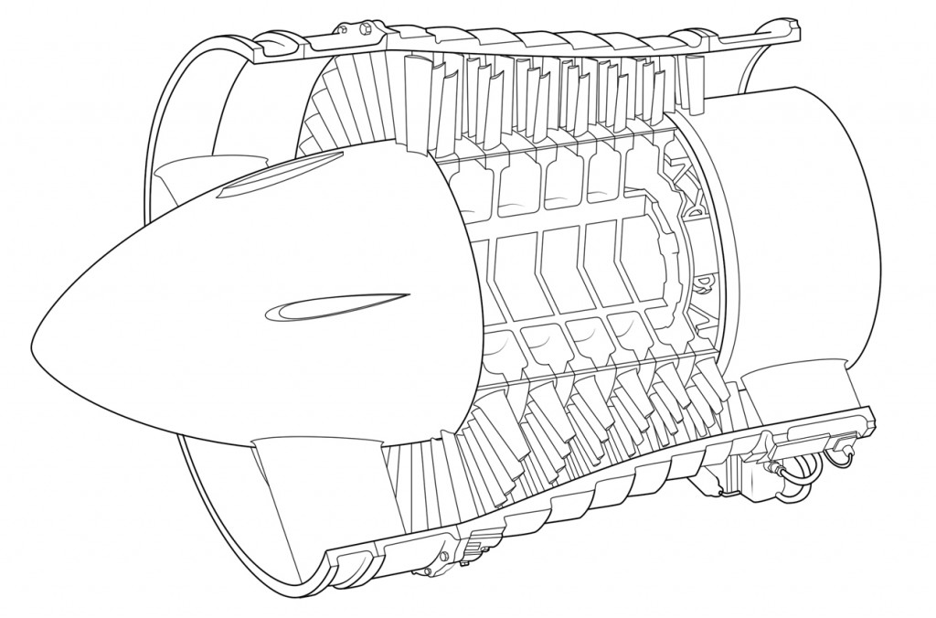
  • Jet Engine Design: The Turbine

    The turbine is at the heart of any jet engine with its primary task being to drive the compressor. As described previously  without the compressor no mechanical work would be done on the fluid prior combustion and the thrust produced would only be a function of the chemical energy stored within the fuel. The hot combustion gases that enter the turbine directly after the combustion chamber are expanded across a series of vanes and stators, known as a stage, similar to the compressor. In the case of a turbine the fluid is expanded to extract useful work and therefore the pressure of the fluid falls across each turbine stage. Since the fluid is not working against an adverse (rising) pressure gradient boundary layer separation over the aerofoils of the turbine blades is not as critical such that  turbine blades can have much more agressive angles of attack with respect to the flow. Consequently, the pressure ratio across a turbine stage can be much higher than across a compressor stage and it quite common for a single turbine stage to drive six or seven compressor stages. The amount of power that can be extracted from a turbine stage is tremendous and a single turbine blade (not the full rotor of blades) may contribute up to 250 bhp [1]. The biggest driver behind the progress in turbine technology since Whittle’s first engine in the 1930’s has been the development of advanced cooling methods and the use of high-temperature alloys.

    Similar to compressors axial turbines seen on most modern jet airliners are more efficient than their radial counterparts at higher flow rates. However, radial turbines are still being used on modern aircraft for auxiliary power units. Figure 1 below shows a single-shaft three-stage axial turbine i.e. the three turbine stages drive all of the compressor stages through a single shaft.

    Fig. 1. Triple Stage Turbine [2]
    Fig. 1. Triple Stage Turbine [2]

    The hot gases that exist the combustion chamber and impinge on the first row of nozzle guide vanes that turn the flow into the rotating turbine blades at the optimal angle to extract the most amount of work. Each stage of vanes and blades expands the flow thereby resulting in a drop in enthalpy (total amount of energy in the combustion gases) and a transfer of work from the fluid to the turbine. For simple jet engines the overall performance of the engine is more effectively enhanced by developing the compressor stages. However for large by-pass turbofan engines turbine aerodynamic design is crucial. Figure 2 shows the velocity triangles for the flow passing through a single turbine stage. Separate turbine rows are typically placed very close together, around 20% of a blade chord [1], and the tangential velocity of the rotor blades ωr\omega r(ω\omega is the rotational speed and rr the radius of the blades) is close to the local speed of sound.

    Fig. 2. Velocity triangles for turbine stage [2]
    Fig. 2. Velocity triangles for turbine stage [2]

    The main function of the stator is not to do work but to add swirl to the flow into order to convert some of its internal heat into kinetic energy. The turbine rotor then extracts work from the flow by removing the kinetic energy associated with the swirl velocity. In the global reference frame of the engine the flow into the stator and rotor is highly unsteady and of great complexity. However, in a frame of reference fixed to a rotating blade it can be assumed to be fairly steady with sufficient accuracy. For the first row of stators (or nozzle guide vanes) the flow impinges parallel to the axial flow direction and is consequently turned through angle βb\beta_b with respect to the axial direction by the stator. Thus the flow leaves the stator at with a velocity VbV_b with respect to the stator which is equivalent to a velocity VbV’_b at an angle βb\beta’_b with respect to the rotating blade. At optimum design condition βb\beta’_b is equal to the angle of rotor blade.  VcV’_c and βc\beta’_c are the relative exit speed and blade angle respectively, such that the turning angle is equal to βbβc\beta’_b-\beta’_c. An important design parameter for turbine performance is the blade coefficient ψ\psi, which is the ratio of the total temperature drop  (which is proportional to the work done) across a stage divided by the kinetic energy of the rotor.

    ψ=cp(TaTc)0.5(ωr)2=2waωr(tanβb+tanβc)\psi=\frac{c_p(T_a – T_c)}{0.5 (\omega r)^2}=\frac{2 w_a}{\omega r}\left(\tan \beta_b + \tan \beta_c\right)

    High efficiency are achieved with lower temperature drops per stage and therefore smaller values of ψ\psi and lower turning angles βbβc\beta’_b – \beta’_c. However large values of ψ\psi are required to reduce the number of stages and keep the weight of the engine down. Consequently a compromise has to be struck between optimising thermodynamic efficiency and weight.

    If the high pressure of the fluid exiting the combustion chamber were expanded in a single stage a very high velocity close to 1500 m/s [1] would be produced, which due to losses associated with supersonic shock waves, would be impossible to use efficiently. Therefore the turbine stages make a series of incremental expansions resulting in flows just over the local speed of sound, which, as shown by the velocity triangles, is apparently reduced on entry to the next stage as a result of the change in reference frame. Thus the velocity triangles show that the velocity leaving the stator VbV_b  is high in the frame of reference appropriate to the stator but much lower when seen at the rotor entry VbV’_b . Similarly the velocity leaving the rotor is high in its relative frame of reference VcV’_c. but lower in the absolute frame appropriate to the stator VcV_c. Thus each of the turbine rows takes in a flow which is almost axial down the engine and turns it towards the tangential thereby reducing the effective cross-sectional flow area, which, by conservation of momentum, must result in an increase in fluid velocity.

    Turbine Stresses

    The turbine inlet blades of the first stage are the most likely to determine the life of the engine since they are exerted to the highest fluid temperatures, highest rotational speeds and highest aerodynamic loads. Stresses in the rotor blades also place restrictions on the allowable blade heights and annulus flow area. The gross of the mechanical stresses arise from the centrifugal stresses of the rotating turbine and bending moments exerted by the flowing gases, which unfortunately are both maximum at the blade root. The problem of centrifugal root stress was previously discussed for compressor blades. The turbine blades are of course tuned such that none of its natural frequencies coincide with any rotational or fluid  excitation frequencies so as to prevent resonant behaviour. The gas turbine produces higher specific power and thus efficiency as the turbine entry temperature (TET) of the gas exiting the combustion chamber is increased. Of course the TET is bounded by the metallurgy of the turbine blade materials. The TET has increased from around 800°C in 1940 to 1500°C in the 1994 Rolls-Royce Trent engine. This development has in part been due to better materials but more importantly through channelling  of cold compressor air to cool the turbine blades.

    In this high temperature environment the life of the turbine blades is limited by creep, which is the continual and gradual extension of a material under constant load over time. Apart from distorting the physical dimensions and thereby reducing performance of the engine, the induced creep stresses exacerbate the centrifugal operating stresses and will therefore lead to premature failure of the material. Under ambient temperature creep is often only a factor for elastomers and other plastics, but at higher temperatures the effects become increasingly more pronounced for metals as well. A rule of thumb is that the blade life is halved (for a specific blade material and cooling technology) for each 10°C rise in temperature of the metal [1]. In the early days of turbine technology blades were forged but later cast for better high temperature performance. It was then found that by elongating the metal crystals along the direction of the span, creating so called directionally solidified blades, resulted in further improvements in creep performance. The standard technique for high-performance blades is to cast the blade out of a single crystal as shown in Figure 3 below. Metals may deform by separate crystals slipping along grain boundaries, such that removing the grain boundaries all together results in great improvements in resisting creep deformation.

    Fig. 3. The microstructure of the three different turbine blades [4].
    Fig. 3. The microstructure of the three different turbine blades [4].

    A typical alloy used for turbine blades today is Inconel, a nickel-based alloying containing 13% chromium, 6% iron, with small amounts of manganese, silicon and copper. These metallurgical advances account for some of the improvements in driving up TET and turbine efficiency. The other very interesting and complicated technology are blade-cooling techniques. But that is a topic for another article all together.

    References

    [1] Rolls-Royce (1996). The Jet Engine. Rolls Royce Technical Publications; 5th ed. edition

    [2] http://aeromodelbasic.blogspot.co.uk/2012/01/turbines.html

    [3] http://web.mit.edu/16.unified/www/FALL/thermodynamics/notes/fig9VelTrianglesTurbine_web.jpg

    [4] http://www.doitpoms.ac.uk/tlplib/creep/images/img014.jpg

  • Jet Engine Detail Design: The Compressor

    In this post the design of jet engine compressors will be discussed leading to the definition of ballpark performance parameters. For smaller engines centrifugal (CF) compressors are used since they can handle smaller flow rates more effectively and are more compact than axial compressors. Axial compressors however have the advantage of a smaller frontal area for a given flow rate, can handle higher flow rates and generally have higher efficiencies than CF compressors. For larger turbines used on civil aircraft the most suitable compressor and turbine will be of the axial type. Early axial compressors were able to raise the pressure of the incoming area around 5-fold, while modern turbofan engines have pressure ratios in excess of 30:1.

    Low pressure axial compressor scheme of the Olympus BOl.1 turbojet. (Photo Credit: Wikipedia)
    Low pressure axial compressor scheme of the Olympus BOl.1 turbojet

    Because the pressure rises in the direction of flow through the compressor there is an acute risk of the boundary layers separating on the compressor blades as they encounter this adverse pressure gradient. When this happens the performance of the compressor drops dramatically and compressor is said to stall. For this reason the compression is spread over a large number of compressor stages such that the smaller incremental increases in pressure across each stage allow engineers to obtain a large overall pressure ratio without incurring stall. A stage consists of a row of rotating blades called the rotor and a row of stationary blades called the stator. Each of these rows may consist of between 30–100 distinct blades and there may be up to 20 stages between the air inlet and compressor outlet. The role of the rotor blades is to accelerate the incoming air in order to increase the kinetic energy of the fluid. Across the stators the fluid is then decelerated and as a consequence the fluid pressure is increased. As the pressure and density increase across each stage the overall flow velocity is kept relatively constant by reducing the height of the blades from stage to stage. Thus the compressor tapers down from inlet to outlet.

    In an attempt to reduce the number of compressor stages for a more compact engine, a designer’s goal is to maximise the pressure ratio across each stage. The stage pressure ratio RR is given by the following expression,

    Rs=[1+ηsUCacpT01(tanb1tanb2)]γγ1R_s=\left[1+\eta_s\frac{UC_a}{c_pT_{01}}(\tan b_1 – \tan b_2)\right]^{\frac{\gamma}{\gamma-1}}

    Where ηs\eta_s is the stage isentropic efficiency, T01T_{01} is the total (stagnation) temperature, UU the rotary speed of the compressor, CaC_a the axial speed of the fluid, cpc_p the coefficient of latent fusion at constant pressure, and b1b_1 and b2b_2 the angle of the rotor blade leading and trailing edge relative to the axial flow direction.


    Diagram of an axial flow compressor. (Photo Credit: Wikipedia)
    Diagram of an axial flow compressor

     The pressure ratio across each stage can be maximised by increasing the rotary speed of the compressor UU, the angle through which the fluid is turned across the rotor blades tanb1tanb2\tan b_1 – \tan b_2 and the axial speed of the fluid CaC_a through the compressor. However there is a limit on the extent of these three parameters.

    1. The blade tip speed and therefore UU is limited by stress considerations at the root. If the fan is assumed to be of constant cross-sectional area then the centrifugal stress at the root is given by,

    σr=rrrtρbΩ2rdr=0.5ρbUt2(1(rrrt)2)\sigma_r=\int_{r_r}^{r_t}\rho_b\Omega^2 r dr = 0.5\rho_b U_t^2\left(1-\left(\frac{r_r}{r_t}\right)^2\right)

    Where UtU_t is the tip speed, ρb\rho_b is the density of the blade, and the ratio rr/rtr_r/r_t is called the root-to-tip ratio of the blade. To prevent the blades from detaching from the hub and destroying the engine this root stress is not allowed to exceed a certain proof stress. It can be seen that the root stress is proportional to the square of the compressor rotational velocity and decreases as the blade length becomes shorter. Since the first compressor blades have the highest blade lengths they limit the maximum tip speed and therefore the efficiency of the compressor. It is therefore common to split the compressor into double or triple spool configurations such as a large fan, intermediate-pressure and high-pressure compressors that are rotating at three different speeds. In this manner the large diameter fan can rotate at lower speeds to satisfy the stress restrictions while the shorter blade high-pressure compressor may rotate at higher speeds.

    However the rotational speed of the fan is typically constrained by more stringent stress considerations. In a turbofan engine the large diameter fan at the front of the engine acts as a single-stage compressor. In modern turbofan engines the fan divides the flow with most of the air going to the bypass duct to a propelling nozzle and only a small portion going into the core. The high root stresses caused by the long fan blades are often exacerbated by bird strikes. For mechanical reasons a lower limit of root-to-tip ratio of 0.35 is often employed. The flow impinging onto the fan is also at a very high Mach number since the cruising speed of civil aircraft is typically around M = 0.83. Supersonic flow inevitably terminates in a shock wave with a resulting increase in pressure and entropy over the compressor blades. Shock waves reduce the efficiency of the compressor blades since they disturb the flow over the profile that lead to boundary layer separation. Furthermore, these shock waves may cause unwanted vibrations of the fan blades that further reduce the efficiency of the compressor and increase noise. Therefore for reasons of efficiency, reducing noise and limiting the damage of bird strikes the tip speed of the fan is restricted, typically a relative Mach number of 1.6 is considered as the upper limit.

    2. The axial speed CaC_a has to be maximised to optimise the pressure ratio and reduce the frontal area of the engine. Similar to the argument given above the axial speed is typically limited by compressibility effects of supersonic flow. As the pressure, static temperature and therefore the speed of sound increases from stage to stage, the compressibility effects are worst in the first stages. For the first stage the air enters axially such that by adding the orthogonal velocity vectors UU and CaC_a we get V2=U2+Ca2V^2 = U^2 + C_a^2 where V is the speed relative to the blade. In modern engines VV may be in the transonic region incurring quite large losses. In this respect twin-spool engines have the advantage that the lower-pressure compressor rotates at a lower speed, which reduces the compressibility problem.

    3. The angle through which the fluid is turned across the rotor blades b is limited by the growth of the boundary layers. Compressor blades are aerofoils that function in the same manner as aeroplane wings. Therefore as the angle of attack or camber of aerofoil is increased to increase the rotation of the flow velocity vector, the adverse pressure gradient across the suction surface increases, until at some point the boundary layer separates. As the boundary layer separates the effective turning angle b is reduced such that the total pressure increase across the stage reduces.

    The limits of UU, CaC_a and b1b2b_1-b_2 all place limits on the maximum pressure ratio that can be achieved in an axial compressor. Typical examples are UU \approx 350 m/s, CaC_a = 200 m/s, b1b2<b_1 – b_2 <45°.

    Compressor blades are typically quite thin and are constructed from lightweight metallic alloys such as aluminium and titanium. The compressor blades feature an aerofoil section as shown in the Figure below. The centrifugal forces that act on the airflow are balanced by high-pressure air towards the tip of the blade. In order to obtain this higher pressure towards the tip the blade must be twisted from root to tip in order to change the angle of incidence on the flow, and therefore control the pressure variation over the blade.


    Key References

    Rolls-Royce (1996). The Jet Engine. Rolls Royce Technical Publications; 5th ed. edition

  • Jet Engine Design and Optimisation

    For aircraft jet propulsion there are in general four distinct designs: the turbojet, turbofan (or bypass engine), turboprop and turboshaft. This post will address the layout and design of the two most common engines used in modern aircraft, the turbojet and turbofan, and explain how their characteristics make each engine applicable for a specific task. Specifically, two important topics are addressed. The first is the multi-shaft engine with separate low-pressure and high-pressure spools and the second is the bypass engine, in which most of the air compressed by a fan bypasses the core combustor and turbine of the engine.

    In general each engine is made up of four essential components: the compressor, combustor, turbine and nozzle as shown in Figure 1. The compressor raises the pressure of the incoming air before combustion, and the turbine, which extracts work from the hot pressurised combustion products, are at the heart of the engine. The role of the power turbine is not to provide thrust but to drive the compressor. The hot pressurised combustion products are expanded through a nozzle to produce thrust. In some military turbojet engines the exhaust velocity and therefore the thrust may be increased by “afterburning” in the exhaust duct.

    Diagram of a typical gas turbine jet engine. Air is compressed by the fan blades as it enters the engine, and it is mixed and burned with fuel in the combustion section. The hot exhaust gases provide forward thrust and turn the turbines which drive the compressor fan blades. (Photo credit: Wikipedia)
    Figure 1. Diagram of a typical gas turbine jet engine. Air is compressed by the fan blades as it enters the engine, and it is mixed and burned with fuel in the combustion section. The hot exhaust gases provide forward thrust and turn the turbines which drive the compressor fan blades.

    1.1 The Turbojet

    The turbojet is the earliest form of the jet engine as developed by Sir Frank Whittle and Hans von Ohain during WWII. It is no longer used for civil aircraft but predominantly used for high-velocity propulsion in military aircraft. Figure 1 shows a cross-sectional drawing of a typical turbojet engine and illustrates the typical layout of a turbojet engine with an axial compressor driven by an axial turbine, all on the same shaft. This assembly of shaft, compressor and turbine is oftentimes referred to as a “spool”. Newer engines typically have two or three spools such that the compression and expansion process in the compressor and turbine are spread over different parts. In this manner a low-pressure (LP) compressor and LP turbine are mounted on one shaft to form the LP spool. The LP shaft passes through the inside of the hollow high-pressure (HP) shaft on which are mounted the HP compressor and HP turbine. The compressor and turbine are split into separate parts to reduce centrifugal stresses in the compressor and turbine blades, and allow different parts of the compressor and turbine to be run at different speeds in order to optimise the running efficiency.

    For sustained supersonic speeds a turbojet engine remains and attractive option for aircraft propulsion. The Rolls-Royce Olympus 593 is a two-shaft example that was used to propel the Concorde to twice the speed of sound.

    1.2 A Note on Efficiency:

    The propulsive or Froude efficiency hph_p of a jet engine is defined by the power output divided by the rate of change of kinetic energy of the air. The kinetic energy of the air represents the power input to the system. The power output PP is the product of force output i.e. the thrust FF and the resulting air speed  UaU_a. Although this is an approximation this equation summarises the essential terms that define aircraft propulsion. The force FF required to accelerate the fluid is given by the momentum equation,

    F=m˙(UjUa)F=\dot{m}(U_j-U_a)

    Where m˙\dot{m} is the mass flow rate of the air through the engine,  UaU_a is the velocity of the air entering and  UjU_j the velocity of the air leaving the engine. Thus there will be an equal and opposite force acting on the engine called the net thrust. The term  m˙Uj\dot{m} U_j is called the gross momentum thrust and m˙Ua\dot{m} U_a is called the ram drag. Thus, for a turbojet the power output is,

    P=FUa=m˙Ua(UjUa)andKE=0.5m˙(Uj2Ua2)P=F U_a = \dot{m} U_a (U_j – U_a) \quad \text{and} \quad KE = 0.5 \dot{m} (U_j^2 – U_a^2)

    So that,

    Np=m˙Ua(UjUa)0.5m˙(Uj2Ua2)=2UaUa+UjN_p = \frac{\dot{m} U_a (U_j-U_a)}{0.5\dot{m} (U_j^2 – U_a^2)} = \frac{2Ua}{Ua + Uj}

    For a fixed airspeed  UaU_a, NpN_p can be increased by reducing  UjU_j. However decreasing  UjU_j decreases the thrust unless m˙\dot{m} is increased. Thus, for civil aircraft when the economy is important m˙\dot{m} is increased using high by-pass ratios of the turbofan, while for military engine where thrust is important low-by pass engines with large exit velocities are employed.

    1.3 Optimisation of the Turbojet

    When optimising the jet engine performance two parameters are typically considered: the specific thrust (ST) of the engine, and specific fuel consumption (SFC), the mass flow rate of fuel required to produce a unit of thrust. Generally speaking turbine designer have two thermodynamic variables to optimise these two entities: the compressor pressure ratio (R) and the turbine inlet temperature (TET). The effects of these two variables on SFC and ST will be considered in turn.

    ST is strongly dependent on TET and TET should be maximised in order to keep the engine as small as possible for a specific amount of thrust. However, an increase in TET will incur a larger SFC at a constant R. On the other hand a gain in ST is generally more important than the penalty of higher SFC, especially at high flight speeds where a small engine is critical to minimise weight and drag.

    Increasing R always causes a reduction in SFC and hence ensuring efficient compression stages is critical for an economic engine. For a fixed value of TET increasing R will initially result in more ST but will eventually cause ST to decrease again. Thus, there exists an optimum value of R, which is the role of the engineer to ascertain. Furthermore, the optimum pressure ratio for maximum ST increases with increasing TET.

    This optimisation of R and TET can of course not be separated from the mechanical design of the engine. Driving up TET requires the use of much more expensive alloys and cooled turbine blades, which invariably lead to an increase in cost, mechanical complexity or otherwise a reduction in engine life. Increasing R will require larger compressors and turbines that incur weight, cost and mechanical complexity penalties.

    Finally for different flight speeds and flight altitudes the performance of the turbojet will vary since the mass flow rate and momentum drag vary with density of the air and forward speed. Gross thrust decreases considerably with increasing altitude due to the decreasing ambient density and pressure, but specific thrust may increase due to a lower engine intake temperature. SFC however is reduced for increasing altitude, a result that was calculated by Frank Whittle as an engineering student, and led to his motivation for developing the jet engine.

    2.1 The Turbofan

    As revealed above the high exit velocity of turbojet engines does not allow high propulsive efficiencies required for civil aircraft. To raise the propulsive efficiency a bypass engine, often known as a turbofan engine, is used.

    The core of the turbofan engine is essentially the same as the turbojet featuring a compressor, combustion chamber and power turbine as shown in Figure 2. However the engine features a second turbine that drives a large fan at the front of the engine. This fan delivers air to a bypass duct that channels air to the exhaust nozzle without passing through a combustion chamber. For this reason designers often refer to the cold flow in the bypass duct and hot flow through the core. Mixing the colder bypass air with the hot exhaust gases from the core results in higher propulsive efficiencies and lower noise levels. Early bypass engines typically had bypass ratios (the mass flow rate of bypass air divided by the mass flow rate of air going through the core) of around 0.3 to 1.5. The arrangements for modern airliners are High-Bypass-Ratio (HBR) engines with a bypass ratio of 5 or even more. In the Rolls Royce RB211 and Trent families the fan is driven at low speed by one turbine, and two internal compressors driven by another two separate turbines to give a triple spool engine.

    Figure 2. Schematic Diagram of Turbofan Engine

    2.2 Optimisation of the Turbofan

    For turbofan design engineers have four major variables to consider: the bypass ratio (BR), overall pressure ratio (OR), fan pressure ratio (FR) and TET. Similar to the turbojet high TET is required for increased thrust. As the FR is increased the thrust contributed by the cold flow is increased while that of the hot flow decreases since more power is required to drive the fan. There is an optimum value of FR for which the total thrust F=Fc+FhF = F_c+ F_h is a maximum. In actual fact the optimum value of FR when FF is a maximum automatically produces minimum SFC if OR and BR are fixed.

    The propulsive efficiency rises and the SFC falls as BR is increased. For laung-haul subsonic aircraft SFC is important to reduce cost. For these engines BR is typically between 4 and 6 and OP and TET are high. Thrust is more important for military aircraft such that BR is typically reduced to 0.5 to 1. BR significantly affects the engine efficiency, appearance, size and weight of the engine. As the weight of the engine increases less payload can be added to the aircraft such that the airlines revenue falls. Second, increasing the lift produced by the wings to carry bigger engines automatically induces more drag. Finally, for practical reasons BR > 10 are not practical with current technology since it would be necessary to install a gear box between the driving power turbine and fan to allow the turbine to run faster. Such a design would most certainly require considerable development time and would probably incur a weight penalty that outweighs the benefits of increasing the BR. Thus optimisation of the engine cannot only be considered in terms of thermodynamic parameters and aircraft manufacturers ultimately decide which engine to install based on what design gives airlines the highest financial yield.


    Key References

    Rolls-Royce (1996). The Jet Engine. Rolls Royce Technical Publications; 5th ed. edition

  • The Birth of the Jet: The Engine that Shrunk the World

    In today’s time it is easy to take for granted the complex inventions that alleviate our everyday life. The modern jet propelled airplanes for example, are one of the biggest drivers behind rapid globalisation and play a major role in world trade. Nevertheless, the development that revolutionised aviation and inaugurated the era of jumbo jets came in a time of European and World conflict. It was at the dawn of World War II that two engineers from opposing sides of the war, separately and unaware of the other’s contribution, engineered the Jet Engine that would shrink the world in the 20th century and set the groundwork for other milestones in aviation such as supersonic flight and space exploration.

    The notion of jet propulsion has been around for centuries. The concept of jet engines can actually be traced back to the first century AD, when Hero of Alexandria introduced the “aeolipile”. This machine used pressurised steam forced through two jet nozzles placed on the surface of a sphere so as to force the sphere to spin rapidly on its axis [1]. Jet propulsion got off to its “flying start” with the Chinese invention of the rocket used for fireworks in the 11th century. By the early 20th century jet propulsion was a known principle and viewed as a potential alternative to standard propeller engines, especially in high-speed flight. By the 1920s jet engines, powered by an external power source, were used to propel racing planes but proved to be inefficient for low-speed flight.

    Heinkel He 178

    On the German side of WWII a young German physicist, Hans von Ohain, was at the forefront of research into jet propulsion [2]. Hans von Ohain was born in Dessau on December 14, 1911 and received his Ph.D. in Physics and Aerodynamics from the University of Göttingen. During his studies he established the notion that one could build “an engine that did not require a propeller.“ Von Ohain’s first attempt to build a jet engine, which he patented in 1936, was not a great success. The jet engine had been built by an automotive engineer, Max Hahn, but ran into serious problems with combustion stability [3]. Most of the fuel would not ignite within the engine but would combust in the outside air. This caused flames to shoot out the back and prompt the electric motor powering the compressor to overheat. When Ernst Heinkel, one of the largest German aircraft manufacturers of the time, heard of von Ohain’s work he recognised the promise of the design and started to provide financial and technical funding [1]. After a two-month period of research on the airflow in the engine Max Hahn, von Ohain and Heinkel’s best engineers completed construction of a totally new engine that ran on hydrogen. As the high-temperature hydrogen exhaust damaged the metal framework, the old HeS 1 engine was refined to run on gasoline, a centrifugal compressor and axial turbine stages. This new engine, the HeS 3b, was then fitted to a new test airframe, the Heinkel He178. On August 27, 1939 the Heinkel He178 took off from Marienehe aerodrom and was thus the first jet-powered airplane. In 1940 the engine designer Anselm Franz developed the Jumo 004 engine with an axial-flow turbojet, as opposed to the centrifugal-flow designs [4] of the original von Ohain engines. This engine was used to propel the Messerschmitt Me262 in 1942, the only jet fighter airplane in WWII.

    At about the same time in England Frank Whittle, born on June 1, 1907 in Earlsdon as the son of a mechanic, developed his version of the jet engine unaware of von Ohain’s achievements. In a 1928 in an astonishing student essay Future Developments in Aircraft Design Whittle showed that at increasing altitudes of flight the lower outside pressure and density of air would reduce drag with subsequent improvements in fuel efficiency and flight speed. In these conditions Whittle contemplated speeds of 600 mph at 60,000 feet when at the time the fastest RAF plane flew at 150 mph at a maximum altitude of 15,000 feet. However, current designs based on the internal combustion engine were being starved of oxygen at higher altitudes, which essentially limited current fighter planes to lower and slower flight conditions. Whittle therefore proposed a new form of propulsion – the jet engine.

    Whittle Jet Engine W2-700
    Whittle Jet Engine W2-700

    Whittle’s patent showing a centrifugal-flow engine with a multi-stage axial followed by a centrifugal compressor was granted in 1932. Unluckily Whittle was unable to excite either RAF nor the government to fund his work. Therefore he, Rolf-Dudley Williams and J. Tinling, two ex-RAF men who were interested in his work, incorporated the Power Jets Ltd. Even though the company only received minimal funding from outside investors, Power Jets were able to complete and run their first engine, the Whittle Unit, on April 12, 1937. This achievement triggered the interest of the Air Ministry, which now started to grant minimal amounts money in order to develop a flyable version. On May 15, 1941 the revised engine W.1 with 3.8 kN thrust and manufactured by Rover was fitted to the Gloster E.28/39 airframe and took off for a flight of about 17 minutes with a maximum speed of 545 km/h. Rolls-Royce then took over the development and production of the Whittle engine, which led to the Whittle-type Rolls-Royce Welland and the W.2 engines [5]. These new designs were used to propel the interceptor Gloster Meteor 1 in 1944.

    After the war the British shared Whittle’s technology with the United States, enabling the engine-builder General Electric (GE) to build jet engines for America’s first jet fighter, the Bell XP-59. Another American jet engine designer Pratt & Whitney improved the fuel economy of jet engines, while a General Electric engineer named Gerhard Neumann introduced the variable stator; preventing jet engines from gulping in too much air and restraining them from losing all their thrust [5].

    During the last 40 years jet engines have been improved in a variety of ways, and have also been combined or replaced with rocket engines. For example, manned superplanes like the rocket-powered X-15 can fly almost 7 times the speed of sound, while the new A380 can transport up to 800 passengers in a luxurious ambience. It is remarkable to say that the early steps taken by Whittle and von Ohain laid the foundation for all these new magnificent aircraft.

    Jet engine
    Diagram of a typical gas turbine jet engine. Air is compressed by the fan blades as it enters the engine, and it is mixed and burned with fuel in the combustion section. The hot exhaust gases provide forward thrust and turn the turbines which drive the compressor fan blades

    Works Cited

    [1] http://en.wikipedia.org/wiki/Jet_engines

    [2] www.centennialofflight.gov/essay/Evolution_of_Technology/jet_engines/Tech24.htm

    [3] http://en.wikipedia.org/wiki/Hans_Joachim_Pabst_von_Ohain

    [4] Huenecke, Klaus. Jet Engines. 1997. UK: Airlife Publishing Ltd.