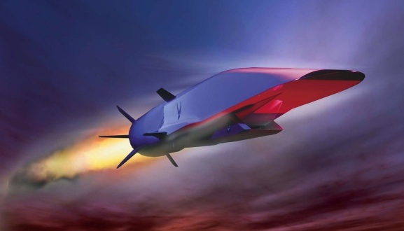
The American Air Force has reported that a test of the unmanned hypersonic X-51A “Waverider” scramjet has failed. During the test flight the aircraft disconnected successfully from the the wing of a B-52 bomber but only 16 seconds later a defect in a control fin caused the “Waverider” to spiral out of control and eventually break up over the Pacific. The test aircraft was planned to reach a top speed of 7000 km/hr and hold Mach 6 for 300 seconds. This recent event continues the series of failed tests that have plagued the project since its first flight in May 2010. Of originally four prototypes the Pentagon now has only 1 test aircraft remaining. In 2004 the older “X-43” scramjet model reached air speeds of up to Mach 10 – equal to around 11,000 km/hr.
Scramjet released from B-52 carrier wing [1]
The Scramjet Technology
A scramjet, or supersonic combustion ramjet, is a development of the ramjet engine in which combustion takes places at supersonic rather than subsonic speeds. Both engine variants require high initial vehicle velocities in order to compress and decelerate the incoming air in a converging chamber. Since the airflow throughout the engine and especially the combustion process remains at supersonic air flow the scramjet can operate more efficiently at very high flight velocities.
A model of the “X-51A Waverider” [1]
The scramjet is solely comprised of a converging inlet, a fuel injection point and a converging nozzle. As the supersonic airflow is compressed the temperature of the fluid rises to such an extent that a simple injection of gaseous fuel is sufficient to combust the chemical with the atmospheric oxygen. The combustion process raises the enthalpy of the fluid such that an expansion throughout the divergent exhaust nozzle leads to incredible acceleration of the air and consequently thrust. The principle of expanding a high-enthalpy fluid to generate thrust is similar to standard turbofan and turbojet engines, only that a scramjet does not use multiple rotating compressor stages in the inlet. As they lack mechanical compressors operation of scramjets is limited to near-hypersonic velocities since the high kinetic energy of a hypersonic flow is required to compress the incoming air to operational conditions. Thus, a scramjet-powered vehicle must be accelerated to the required velocity by some other means of propulsion.
Comparison of Turbojet, Ramjet and Scramjet [2]
The elimination of all moving parts greatly reduces the complexity, weight and susceptibility to mechanical failure of the engine. Furthermore, in turbofans and turbojets the rotating compressors are driven by turbine stages located in the diverging nozzle. The turbine stages are powered by the accelerating exhaust gases and therefore reduce the available energy output. In turbofan and turbojet engines the energy output and thrust can be directly increased by raising the turbine entry temperature i.e. burning more fuel or guaranteeing a more efficient combustion process. Throughout the years turbine entry temperatures have approached the melting point of the turbine blade metals, thus increasing the risk of static and creep failure at the highly stressed turbine inner hub. In the past, solutions to this problem included using nickel-based superalloys, thermal barrier coatings, or casting the turbine blade as a single crystal in order to remove the deformation planes at the grain boundaries. Today almost all turbine blades also feature direct air film cooling around the blades. In this technique cooler air from the compressor stages is bled to and then through channels in the turbine blades and finally allowed to flow out through tiny holes on the turbine blade surface. Ultimately this bled air is then lost from doing any useful work as combusted air. Finally, as turbofan and turbojet engines approach Mach 1 there is an issue with the flow becoming supersonic at the tips of the rotating compressor blades. Any supersonic flow will terminate in a shockwave that will disturb the uniformity of the flow throughout the compressor and cause pressure surges. This will reduce the efficiency of the compressor or even cause single blades to break off.
Thus the higher efficiency and reduced complexity makes the scramjet a better solution for hypersonic propulsion. Currently the scramjet technology would facilitate sudden airborne attacks but is not yet suited for manned flight.
Throughout the last four decades the exploitation of fibre-reinforced plastics (FRP) in engineering structures has been steadily diversifying from sports equipment and high performance racing cars, to helicopters and most recently commercial aeroplanes. Composite materials are essentially a combination of two or more dissimilar materials that are used together in order to combine best properties, or impart a new set of characteristics that neither of the constituent materials could achieve on their own. Engineering composites are typically built-up from individual plies that take the form of continuous, straight fibres (eg. carbon, glass, aramid etc.) embedded in a host polymer matrix (eg. phenolic, polyester, epoxy etc.), which are laminated layer-by-layer in order to built up the final material/structure.
All manufacturing processes are subject to a certain degree of variability. Composite materials differ from most metallic manufacturing routes in that the material is generated at the same time as the structural geometry of the part. In the aerospace industry autoclave components of pre-impregnated reinforcements are the dominant mouldings being used. In this case the hardest variable to control is the thickness dimension and this will be the major concern of this article.
Lean manufacturing calls for variability on thickness expressed as a standard deviation of 1/6th the drawing tolerance – the “6-Sigma” tolerance band – giving a thickness defect rate of 1 in 1,000,000. In reality current thickness defect rates are in the range of 1 in 10 for composite components (1). The biggest influence on laminate thickness is the consolidation pressure. As the consolidation pressure is increased the laminate is compacted more and thus more resin may be bled out of the prepreg. As a result the volume fraction of fiber can vary from just around 50% at 1 bar consolidation to almost 70% at 6 bar. Such large variations in volume fraction will naturally influence the consolidation thickness. The external pressure “felt” by the laminate is not just a function of the target autoclave setting. Insufficient contact between the vacuum bag and the laminate and wrinkles in the bag will greatly reduce the consolidation pressure experienced by the laminate. Since the vacuum bag application is a manual process and the bagging material can be quite flimsy certain amount of wrinkling is inevitable. Thus it can be very difficult to reduce this type of variability and in the worst-case defects such as delaminated plies may occur.
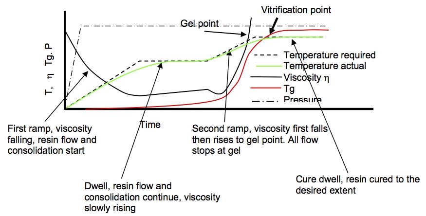
During curing the external temperature is typically ramped up in two stages and held constant in between, the so-called “dwell period”, in order to allow the actual mould temperature to catch-up and ensure full consolidation and cure. During the early parts of the cure the resin viscosity will first reduce as a result of the increasing temperature but then increase suddenly as the mould temperature reaches the gelation point and thus causes the resin to solidify. When the resin viscosity is low internal flows of resin will occur.
Composite Consolidation Programme: Variation of Viscosity with Temperature (3)
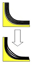
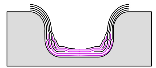
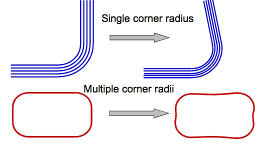
Around corners the difficulty of preventing fibre wrinkling or fibre bridging is added. If plies cannot slip over each other as they consolidate over inside radii, fibre bridging will occur and the laminate will get thicker in the corner. The fibres that bridge the radius will directly react the consolidation pressure leading to a reduced resin pressure beneath the bridged fibres. Resin will, therefore, tend to flow towards this region of bridged fibres but if this does not sufficiently occur high local voidage will result.
Fibre Bridging (3)
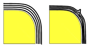
Fibre Wrinkling (3)
Upon consolidation the resin will start to shrink and since it is constrained, the bridged pocket will be exerted under tensile stress. This may cause cracking in the brittle resin and thus cause internal failure before any external load has been applied on the part. Fibre bridging may be reduced by using rollers to press the fabric into the corner or by incorporating slip-lines into the layup. However, especially in the latter case this will complicate the layup and increase manufacturing times.
Slip Lines in Layup (3)
Equally, if plies cannot slip over external radii then fibre wrinkling or “earing” will occur. Although this will not produce a resin sink the wrinkled area will be voidy and have poorly controlled fibre orientation leading to a reduction in mechanical properties. Fibre wrinkling may also be exacerbated by wrinkles in the vacuum bag over the corner.
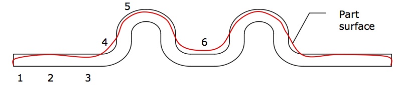
Taking the example of the component below the real laminate thickness and target thickness can be widely different. In zone 1 the laminate is likely to be thinner as a result of resin bleeding out of the component unless some sort of resin dam is used. Zones 3 and 5 are likely to be thinner due to resin flow from these areas into the resin sink over the internal radii at zone 4. Ideally the effects of internal and external radii would cancel out at zones 4 and 5 but inaccuracies in the layup or induced tensions in the plies will typically mitigate this. The most critical section of the component is undoubtedly zone 6, where high voidage is very likely due to the difficulty of bleeding sufficient resin into the area and the two adjacent internal radii.
Thickness Variation in Composite Moulding (3)
Thickness deviations are only one form of variability. Other defects may stem from part design, manufacturing design, the lay-up process or the autoclave process. To produce reliable components with tightly toleranced dimensions lay-ups are typically made balanced (equal number of ±Angle° plies) and symmetric about the mid-plane in order to avoid thermally induced distortions. Unbalanced or unsymmetric laminates manufactured as plates on flat tools will warp and twist as a result of the different thermal expansion coefficients of different layers. However, if the resin content varies between different plies the thermal properties will naturally vary and the laminate will be unbalanced. For a typical pre-preg the weight/unit area tolerance limits can be up to 5% on both pre-preg and fibre weight, and resin contents may even have a slightly wider tolerance band (1). Considering that resin and fibre contents directly influence the mechanical properties of the composite it can be quite challenging to decrease variability and guarantee reliable components with such a wide tolerance band.
Additional distortions arise if aluminium or steel tooling is used. Metal tools have higher coefficients of thermal expansion than composites and cure in the autoclave can occur at elevated temperatures of typically 180°C. Therefore the tooling will expand more than the composite, putting strains onto the outermost ply. These surface strains may be exacerbated by local features such as a corners and joggles.
A considerable amount of variability around corners is the so-called “spring-in” effect. As the laminate cools down from cure it will contract far more through the thickness than in plane. In order to maintain continuity of the profile without causing residual stresses the corner angles will close up. This can result in changes of corner angle of about 1° for 150°C change in temperature. Other defects such as fibre wrinkling or bridging will worsen this effect. In general it is very difficult to accurately predict what will happen for certain geometries.
Composite Spring-In (3)
In addition, other sources of defects include:
Surface scratches, depressions and dents
Delaminations between plies or voids
Material inclusion within the layup such as a ruler
Undercure or overcure (burning)
Tool drop or other impact events that can cause internal resin damage or delaminations
In general most of these defects can be controlled by well-trained and highly motivated factory staff. Engineers and factory management should work together to ensure that all employees involved with the layup and curing process are aware of all possible sources of variability and how to mitigate these. In this respect detailed technical training entrusts more responsibility on the shoulders of employees and gives the staff the deserved recognition of being an important cog in the works of the company. Furthermore, the importance of a well-lit, comfortable working environment and positive atmosphere should not be understated and can go a long way to guaranteeing high-quality mouldings. A well-trained, highly motivated and happy staff is the first line of defence against poor parts.
Next it is important to follow a concurrent design philosophy throughout the development process of a component. Thus the design, stress, manufacturing and quality control engineers must simultaneously work together in order to come up with a solution that fulfils all functional needs but can also be manufactured to a profit without unnecessary defects. The classical philosophy of separately designing a functional component, which is handed to the production engineers, makes manufacturing high-quality laminates incredibly difficult and will incur significant secondary costs.
Finally, specific details of possible sources of variability can then be handled on a case-by-case basis. Thus the component’s shape and type of prepreg to be used will influence the mould material shape design; curing temperature and pressure; possible inclusion of slip lines and laminate stacking sequence as discussed above. In conclusion, manufacturing high-quality laminates for the aerospace industry is not an easy task and is even more daunting considering the size of the current all composite Boeing 787 Dreamliner and Airbus A350 XWB projects. Each design decision must be weighed against the influence on manufacturing process and every little detail is important!
References
(1) Potter, Kevin (1996). An Introduction to Composite Products: Design, Development and Manufacture. Springer, 5th Ed. Chapman & Hall, London.
Throughout the last four decades the exploitation of fibre-reinforced plastics (FRP) in engineering structures has been steadily diversifying from sports equipment and high performance racing cars, to helicopters and most recently commercial aeroplanes. Composite materials are essentially a combination of two or more dissimilar materials that are used together in order to combine best properties, or impart a new set of characteristics that neither of the constituent materials could achieve on their own. Engineering composites are typically built-up from individual plies that take the form of continuous, straight fibres (eg. carbon, glass, aramid etc.) embedded in a host polymer matrix (eg. phenolic, polyester, epoxy etc.), which are laminated layer-by-layer in order to built up the final material/structure.
An example of a composite laminate (1)
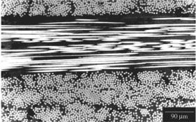
Cross-Section of composite laminate. The individual fibres and surrounding matrix are clearly discernible (2)
In the aerospace industry the benefits of exploiting the excellent specific strength and stiffness properties (strength and stiffness per unit weight) of composites in terms of lightweight structural design are immediately apparent. Furthermore, the laminated nature of high performance composite materials enables the designer to tailor optimum mechanical properties by orientating the fibre direction with the primary load paths. As a result, the first generation of commercial aircraft that contain large proportions of composite parts, such as the Boeing 787 Dreamliner and Airbus A350 XWB, are planned to enter service in the near future. Other advantages of fibre reinforced plastics, such as the relative ease to manufacture complex shapes, and their excellent fatigue and corrosion resistance, have made FRP composites increasingly attractive in the renewable energy sector.
Composite materials have actually been around for quite a long time. As early as 3000 B.C. the ancient Egyptians embedded straw in their mud bricks in order to control shrinkage cracks and improve the tensile strength. Furthermore, papyrus based cartonage and paper maché were used to make mummy cases. In fact, manufacturing tubular shells using metals is quite difficult such that this ancient approach remains an important exploitation of composites today. Of course none of these materials would be suitable for the high performance requirements of the aerospace industry.
Mud and Straw Brick (3)
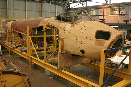
It was not until the invention of phenolic resin in 1909 that composites took-off in aircraft. The most famous example was the deHavilland Albatross transport aircraft manufactured from a ply-balsa-ply sandwich fuselage construction, which was later developed into the deHavilland Mosquito multi-role combat aircraft for WWII. The large-scale wooden construction made the Mosquito extremely light, fast and agile. Furthermore, the Mosquito was cheaper than its metallic counterparts and allowed highly skilled carpenters from all over the UK to be contracted to help with the war effort. One disadvantage of early phenolic resins was their inability to cope with hot-wet conditions such that the Mosquito became notorious for disintegrating in mid-air in the Pacific War arena.
DeHavilland Mosquito Timber Fuselage (4)
Since the development of carbon and glass fibres in the 1950’s the aerospace industry is steadily moving towards “all-composite” civil aircraft. The most common fibre and resin types used today are:
Fibres
Glass
Carbon
Aramid – Kevlar™
Diameter ≈ 10 mm
Diameter ≈ 8 mm
Stiffness ≈ 125GPa in tension
Strength > 3GPa due to lack of defects on small diameter fibre
Strength > 5GPa due to highly aligned planes of graphite
Strength > 3GPa because of highly aligned linear polymer chains
Stiffness ≈ 70 GPa for cheaper E-glass and 85 GPa for more expensive R- or S – Glass
Stiffness ≈ 160-700 GPa but 230-400 GPa is the usual
Much weaker and less stiff in compression as linear polymer chains come apart
Susceptible to environmental attack and fatigue
Not susceptible to degradation by chemicals and good in fatigue
Susceptible to degradation by UV light and moisture
Fibres need silane treatment to bond well to matrix
Fibres bond well with surface treatment
Fibres do not bond well at all leading to a weak fibre/matrix interface
Used in boats, wind turbine blades and other cost critical applications
Expensive material cost limits use to high performance applications were the higher mechanical properties are justified i.e. Racecars, aerospace etc.
Weak interface gives excellent energy absorption. Thus used for bullet-proof vests, helmets and impact protection on aircraft
Matrix
Phenolic
Polyester
Epoxy
First modern resin
Most commonly used matrix
Most common in aerospace
Tends to be brittle
Resin can be quite tough
Can be made quite tough
Wets out fibres badly
Wets out reinforcement very well
Wets out reinforcements very well
Good chemical, heat and fire resistance and don’t produce toxic gases in a fire
Poor chemical resistance and burns very easily
Good chemical resistance but will burn
Thus used in aircraft interiors
Very cheap resin used alongside glass fibres in boat hulls, wind turbine blades and other cost critical applications
Generally used in combination with carbon fibre for high performance, lightweight applications
The shift from metallic to composite construction has naturally induced a change in the design methodology of aircraft components. It has to be borne in mind that not only the mechanical properties of composites differ from those of metals, but that a whole range of physical and chemical properties are different.
– All composites have relatively low through-thickness thermal conductivities and thermal expansion coefficients in and out of plane may be widely different. Therefore thermal expansion mismatch stresses at attachment points can be a problem.
– Composites can be made with very high translucency to electromagnetic radiation eg. X-Ray.
– Electrical conductivity of composites is generally fairly low. Consequently, a copper mesh is often integrated in aerospace laminates to protect against lightning strike damage. However, this compromises a lot of the potential weight savings.
– Direct contact between carbon fibre reinforced plastics and aluminium components will corrode the aluminium over time. Therefore contact between carbon and aluminium at lug attachments and joints has to be prevented.
– All resins pick up water and their properties change as a result of this.
– Composites are not very resistant to mechanical wear effects. External surfaces may need treatment prior to painting.
– Composites tend to have relatively low stiffnesses on an absolute basis, from <10% to about 60% of steel.
– The failure modes in composites are very diverse and include fibre failure, resin failure, fibre/matrix debonding, delaminations etc., which generally increases the analytical workload. Often these failure modes are related such that it can be difficult to exactly predict the failure load.
– Composites will absorb impact energy by damage modes rather than local plastic deformation. This means failure is typically sudden and catastrophic without any prior warning that the structure has been overloaded.
– Fatigue, stress rupture and creep resistance varies from rather poor for glass FRP in wet conditions to excellent for many carbon FRP layups.
Especially due the uncertainty of correctly modelling the complicated failure modes, engineers have tended to revert to a “black” aluminium approach that has inhibited the full exploitation of composite materials in terms of potential weight savings. However, the ongoing research activities into advanced composites and increasing teaching in higher education will hope to resolve these issues in the near future.
Although the exploitation of advanced composite materials in the aerospace industry is steadily increasing, high strength metallic materials, particularly aluminium alloys, are still the first choice for large-scale fleets such as the Airbus A320 and the Boeing 737. Since the introduction of stressed-skin “semi-monocoque” aircraft structures in the 1930’s the structural design philosophy has developed considerably, and the history of this development has been greatly influenced by in-service failures.
1930 – 1940: Early commercial transport aircraft. Design and structural design focus primarily on static strength with little regard to long- term material degradation by mechanical fatigue i.e. cracking, creep etc.
1940 – mid 1950’s: Aluminium alloys with higher static strength are developed to reduce material usage but with little improvements or even reductions in fatigue strength. A number of catastrophic in-service failures leads to the increasing awareness of fatigue failure for safe design.
mid 1950’s – present: The terms “fail-safe” and “damage tolerant” design are coined, which account for damaged and cracked structures before service. The embedded damage is expected grow during service as a result of cyclic loading. Safety is ensured by pre-service testing to ascertain the extent of damage that will induce ultimate failure, and regular inspection, repair and replacements in-service before the critical damage size is reached.
Four case studies are generally considered to be critical milestones in the development of current structural design for metallic aircraft structures (2-5).
Table 1. Four milestone aircraft failures that influenced future aircraft structural design (1)
year
aircraft failure
lessons learned
1954
Two DeHavilland Comet aircraft crash as a result of fuselage explosions
First indicator and seed for awareness of finite aircraft fatigue life as a critical design factor in modern thin-skinned aircraft shell structures. Development of full-scale fatigue testing.
1969
F-111 wing failure as a result of an undetected initial material flaw
Initial material flaws and defects have to be accounted for prior to service and monitored in-service. Aircraft should be damage tolerant.
1977
Boing 707 tailplane lost as a result of fatigue failure in a spar
The older the aircraft the more susceptible it is to fatigue cracking. Also crack growth accelerates with increasing size.
1988
Boeing 737 loses part of fuselage skin due to multiple fatigue cracks in spars
Multiple-site fatigue damage may occur in ageing aircraft. Joints in the structure are especially critical.
References
(1) R.J.H Wanhill (2002). Milestone Case Histories in Aircraft Structural Design. National Aerospace Laboratory. NLR-TP-2002-521
(2) J. Schijve (1994). Fatigue of aircraft materials and structures. Int. J. Fatigue. Vol. 16 (1) pp. 21-32
(3) T. Swift (1987). Damage tolerance in pressurised fuselages. 11th Plantema Memorial Lecture. New Materials and Fatigue Resistant Aircraft Design (ed. D L Simpson) pp 1 – 7. Engineering Materials Advisory Services Ltd., Warley, UK.
(4) A.J. McEvily (2002). Metal Failures: Mechanisms, Analysis, Prevention. Chapter 1. John Wiley & Sons, Inc. New York, USA
(5) A.F. Blom (2002) Fatigue science and engineering – achievements and challenges. 18th Plantema Memorial Lecture, ICAF’2001: Design for Durability in the Digital Age. Vol I, pp 3-64. Toulouse, France.
For many years engineers have been trying to harness mechanical work from thermal energy by taking advantage of the crystallographic phase change of shape memory alloys (SMA’s). SMA’s can exhibit strains of up to 8% actuated by a transformation of the internal crystal structure from martensite to austenite as the metal is heated. This solid state phase change causes a shearing of the internal structure that deforms the material. By introducing additional internal stresses the alloy can be “trained” to transition between two states by applying temperature changes. One of the most well-known projects of the past is the Smart Aircraft and Marine Propulsion System demonstration (SAMPSON), intending to demonstrate the potential of SMA’s in tailoring the geometry of jet-propulsion systems through a series of experiments.
Boeing variable geometry chevron, flight testing (1)
One experiment investigated the utilisation of bending actuation of SMA’s to optimise the compromise between noise-mitigation at take-off and landing (noise levels are strictly regulated by civil agencies), and maximum thrust at cruise altitude. To achieve this Boeing formed the trailing edge of the exhaust nozzles on commercial turbo-fat jet engines in a triangular “chevron” shape (Figure 1) designed to be reconfigurable by actuation of embedded SMA beam components. The “Variable Geometry Chevrons” (Figure 2) feature NiTi (60% Ni and 40% Ti by weight) SMA beam elements encased in the composite chevrons in a complex 3-D configuration to induce the necessary bending moments to force the chevrons inwards into the bypass flow at low altitudes and low speeds where the engine temperature is high. The intruding chevrons cause a disturbance in the bypass flow, inducing a broader diffusion and mixing of the hot exhaust gases with the cooler bypass flow. Thereby the shear stress between the two different-velocity flows is decreased leading to a reduction in the noise level.
FEA analysis of Boeing Variable Geometry Chevron with SMA strips shown (1)
At higher altitudes and high speeds where the engine temperature is low, the chevrons relax and straighten-out. This guarantees a smooth exit flow that decreases the pressure difference between the inlet and exit of the engine and thus increases the engine thrust. In the original work published by Mabe et al. (2005) the system is designed for both autonomous operation as well as controlled actuation using heaters installed in the engine casing with a closed loop controller to maintain optimum in-flight tip immersions. A parametric study showed that during cruise marginal immersion helped to reduce shock cell noise with negligible thrust penalty.
NASA developed an active bending chevron system by embedding tensile pre-stressed NiTinol SMA strips on one side of the neutral axis of the composite laminate. Actively controlled thermal excitation thus causes the SMA actuators to attempt recovery of the pre-strain constrained by the bond to the host material. The resulting asymmetry in thermal stress causes a moment that deflects the structure. The aerodynamic load due to engine flow and the strain energy stored in the deformed host composite are used to restore the structure to the un-actuated configuration.
The simple design appeals by its lightweight construction with low part count and opportunity to be fully integrated into an autonomous morphing system. The “Variable Geometry Chevron” demonstrates the excellent potential of SMA’s to be integrated in composite laminates to provide internal actuation for smart structures.
References
(1) DJ Hartl & DC Lagoudas (2007). Aerospace applications of shape memory alloys. Proc. IMechE Vol. 221 Part G: J. Aerospace Engineering
The exploitation of conventional, continuous fibre-reinforced plastics in engineering structures has been steadily diversifying from sports equipment and high performance racing cars, to helicopters and most recently commercial aeroplanes. The main benefits of composite materials, such as their excellent specific strength and stiffness properties, must be viewed with respect to in-plane fibre-direction applications. However, if a composite plate is subjected to significant out-of-plane stresses subsurface delaminations may develop between layers due to the weak through-thickness cohesive strength of the composite (2). Previously, techniques such as Z – pinning, stitching and 3D – braiding have been investigated to improve through-thickness properties but these tend to reduce the in-plane performance of the laminate by damaging primary fibres and inducing fibre waviness (1).
Carbon Nanotube interfacial strengthening
Throughout the last decade the huge interest in Carbon Nanotubes (CNT) has been fuel by their extraordinary intrinsic mechanical, electrical and thermal properties, which make them ideal candidates for multifunctional structures (3). To overcome the weakness of interlaminar strength considerable research has been conducted to develop hierarchical composite structures by using nanoscale CNT reinforcement alongside microscale carbon and glass fibers. Examples in nature such as cell walls and animal shells show that excellent mechanical properties can be obtained from spreading reinforcement over a number of length scales, even if the original constituents are fairly weak (4). This paper reviews the progress in developing such hierarchical composites to improve delamination resistance and through-thickness properties by intra- and interlaminar reinforcement of multiwall carbon nanotubes (MWCNT).
In an attempt to improve the through-thickness properties the introduction of CNTs should,
Ideally be attached radial to the primary fibres and extend into the surrounding matrix to stiffen the fibre/matrix interface, improve the primary fibre surface area and facilitate mechanical interlocking, all of which improves stress transfer.
Result in a uniform distribution of CNTs.
Not reduce the in-plane laminate properties.
Not introduce other secondary or additional modes of failure by damaging the primary fibres.
Allow a scalable, straightforward processing technique that can be easily incorporated with conventional manufacturing processes such as VARTM or pre-preg.
In the literature there are currently two popular methods to achieve this,
Dispersing CNTs in a polymer matrix followed by infusion of pre-forms with the CNT-reinforced resin,
A direct attachment of CNTs onto the external surface of the primary fibres subsequently infused with a pristine resin.
In the following sections the details of the two manufacturing approaches (shown schematically in Figure 1) are outlined and the implications of each approach on through-thickness performance such as interlaminar shear strength, and Mode I and Mode II critical fracture energy discussed.
Fig. 1. Schematic diagram of conventional CFRP and hierarchical CFRP with CNTs in matrix and grown on fibres (4).
CNT-reinforced Matrix
The simplest method to manufacture hierarchical nanocomposites is by mechanically or ultrasonically shear-mixing CNTs into low-viscosity thermosetting resins, and then infusing or impregnating the primary fibre stack using conventional techniques such as VARTM (5; 6; 7). To date the most uniform dispersion of MWCNTs throughout the matrix have been achieved by shear mixing using a three-roll mill (8; 9). On the other hand this approach is limited to short CNTs < 1 mm at low volume fractions of 1 – 2%, which greatly limits the reinforcement potential. Higher volume fractions are to date not possible since the viscosity of the matrix increases rapidly with CNT content leading to incomplete infusion (10) or CNT agglomeration/depletion in different areas of the fabric (11).
Flexural tests of hierarchical composites with glass and carbon primary fibres show that the in-plane stiffness and strength are not impaired by the MWCNTs (5; 8). Qiu et al. (5) actually showed an improvement in tensile strength and stiffness of a glass-fibre composite of 15.9% and 27.2% respectively, while Veedu et al. (12) showed improvements of 142% and 5% for carbon composites. Most importantly, as tabulated in Table 1 short beam shear (SBS) and compression shear tests (CST) have shown increases in the matrix-dominated interlaminar shear strength (ILSS) between 8% and 33%. Scanning electron microscopy (SEM) images show that the MWCNTs in the resin lead to better fibre-to-matrix adhesion as well as pullout and rupture of the MWCNTs before final matrix failure, which consumes additional fracture energy (Figure 2).
Fig. 2. SEM images showing much more matrix stuck to the fracture surface of CNT reinforced matrix suggesting better matrix/fibre adhesion (7)
The SEM images also indicate that the alignment of the CNTs is heavily influenced by the direction of the resin flow during infusion and local orientation of the primary fibres (4). As resin infusion generally occurs in the through-thickness direction the VARTM approach can give some control in aligning the CNTs in the preferred direction for improving transverse properties, although a certain degree of random alignment remains. Furthermore, one study has shown (5) that functionalised MWCNTs resulted in slightly higher SBS shear modulus and strength (~3%) compared to a pristine un-functionalised MWCNTs. Using SEM imagery the authors showed that this stemmed from a superior interfacial bonding between the CNTs and the matrix.
Delamination resistance is generally investigated using Mode – I double cantilever beam (DCB) tests and Mode – II end-notched flexure (ENF) tests. Table 1 summarises the significant improvements of up to 98% and 75% for Mode I and Mode II fracture toughness respectively compared to non-hierarchical composites. The characterisation of the fracture surfaces using SEM imagery has shown that the additional pullout and bridging of the CNT is responsible for the toughening. Similarly, Garcia et al. (13) have developed an efficient technique of growing CNT mats on growth substrates and then “transfer printing” the CNT mats in between tacky pre-preg plies using a roller. Since this process better controls the CNT alignment in the through-thickness direction much higher improvements of fracture toughness of 152% in Mode I and 214% in Mode II were observed. However, the process of “transfer printing” CNT films at every ply interface is a very time consuming endeavour and may therefore not be as applicable to scalable industrial integration as the VARTM process.
Table 1. Improvements in ILSS and delamination resistance of CNT-reinforced composites.
Fibre
Matrix
Nanofiller
Nano- Reinforced Region
Test Method
Improve-ment
Ref. And Year
woven glass
VARTM epoxy
1 wt% of pristine and functionalised MWCNT
entire matrix
SBS (ILSS)
7.9%
(5), 2007
woven glass
epoxy
0.5-2 wt% MWCNTs
entire matrix
Compression Shear Test (ILSS)
9.7% (0.5%)
20.5 (1%)
33% (2%)
(14), 2008
carbon
epoxy
5 wt% cup stacked CNTs
entire matrix
DCB (Mode I)
–
ENF (Mode II)
98%
–
30%
(15), 2007
carbon
epoxy
1 wt% MWCNTs
entire matrix
DCB (Mode I)
–
ENF (Mode II)
60%
–
75%
(16), 2009
UD carbon
pre-preg epoxy
~1% CNT forests
layer between pre-preg plies
DCB (Mode I)
–
ENF (Mode II)
152%
–
214%
(13), 2008
The fabrication of hierarchical composites by impregnating microscale primary fibres with nanoscale-modified resins is limited to maintaining low matrix viscosities. Furthermore, resin flow during impregnation tends to align CNTs parallel to the primary fibre direction, the least desirable orientation for improving through-thickness properties. In this respect growing or “grafting” CNTs directly onto the surfaces of primary fibres followed by infusion with a pristine, low-viscosity matrix allows higher volume fractions and is ideal for orientating fibres radial to the primary fibres. Furthermore, this approach overcomes the problems of CNT agglomeration or self-assembly into bundles as observed when CNT are freely dispersed in a matrix. Three techniques for attaching CNTs onto fibres were found to be most popular in the literature: CNT-modified Fibres
Direct growth of CNTs onto fibres via Chemical or Thermal Vapour Deposition (CVD and TVD) (12)
Electrophoretic deposition (EPD) (6)
Coating of primary fibres with CNT-modified sizing agents (7)
The first example of synthesising CNTs onto carbon fibres via CVD was conducted in 1991 by Downs and Baker (18). In this approach the primary glass or carbon fibres are initially oxidised with nitric acid and the iron catalysts then deposited onto the fibres using incipient wetness techniques such as sputtering, thermal evaporation or electrodeposition (4). The ultimate result is the growth of highly aligned and dense CNT forests onto fibre cloths (Figure 3) that are then stacked and impregnated by infusion techniques such as VARTM (12). Experiments have shown that the CNT forests are efficiently wet-out by liquid resins and polymer melts as a result of capillary forces (6; 19).
Fig. 3. SEM images showing CNT forests (b) grown in woven pristine fibre cloth (a) (12)
Recently, Injection CVD (ICVD) techniques have been favoured to then grow the CNTs on the primary fibres via a pyrolysis of solutions containing a catalyst precursor and a hydrocarbon source (20). The ICVD technique has resulted in better degree of orientation and growth of longer CNTs compared to classical CVD approach.
The most crucial parameters in grafting CNTs onto glass or carbon fibres are,
Choosing a good catalyst for strong anchoring interaction between CNTs and fibres to maximise stress transfer and reduce damage during manufacturing processes,
While
At the same time prevent oxidation damage to the primary fibres by to aggressive a catalyst.
Fig. 4. Electrophoresis (6)
Oxidation and gasification are especially problematic for carbon fibres since the active catalysts deposited onto the fibres etch into the surface and thus may reduce their strength by up to 55% (4). As a solution Bekyarova et al. (6) selectively deposited multi- and single-walled CNTs onto woven carbon fabric using electrophoresis. In this approach MWCNTs are first produced as is using a classical CVD process and then dispersed in an aqueous media between two negative electrodes to charge the CNTs (Figure 4). The dry carbon fabric was then immersed in the CNT doped media and sandwiched between two steel plates connected to a positive charge. Driven by the electric potential, the CNTs are thus deposited onto the carbon cloth and the CNT-carbon fibre performs then infused with epoxy using VARTM. A very simple approach has been presented by Zhu et al. (7) who sprayed nanotubes directly onto woven fibers prior to VARTM processing. The drawback of this technique compared with direct growth methods is relatively little control over the CNT orientation (4).
The pioneering work of Downs and Baker (21) reported a 4.75x increase in interfacial shear strength (IFSS) of a nanofibre-grafted carbon composite, although such incredible improvements have not been repeated thus far. Table 2 summarises interlaminar and delamination resistance enhancements taken from different sources in the literature and based on multiple primary fibre, CNT and matrix combinations. Veedu et al. (12) showed improvements of 348% and 54% for GICand GIIC respectively for MWCNT enhanced SiC woven fabrics using a classical CVD technique; Bekyarova et al. have found improvements of 27% in ILSS for CNT enhanced carbon fabrics using electrophoresis deposition; while Zhu et al. demonstrated improvements of 45% in ILSS of MWNT doped glass fiber reinforced vinyl ester composites using a simple spray up with only 0.015 wt% of CNTs. In all three studies SEM imagery showed that the improvements arise from the increased surface area of the primary fibres and excellent wettability, which facilitates a strong bond between fibres and matrix by mechanical interlocking.
Based on these results the general consensus is that the damage tolerance of a structure can readily be improved by CNT grafting (4). However, there is also a large variability in the results arising from the different manufacturing processes, material combinations and CNT loadings applied that conceal the exact effectiveness of the method. There is agreement that the degree of enhancement is greatly dependent on the orientation and length of the grafted CNTs and further experimental research is required to ascertain the optimal morphology and manufacturing technique to achieve this (4).
Table 2. Improvements in interlaminar strength and delamination resistance for nano-grafted composites.
Fibre
Matrix
Nanofiller
Manufacturing Technique
Test Method
ILSS Improv.
Ref. And Year
woven glass
vinyl ester
0.015% SWCNTs and MWCNTs
Spray-up between plies
SBS
20-45%
(7), 2007
carbon
epoxy
0.25 wt% MWCNTS
Electro-phoresis
SBS
27%
(6), 2006
SiC
epoxy
2 wt% MWCNTs
CVD
DCB (Mode I)
–
ENF (Mode II)
348%
–
54%
(12), 2006
Perspectives
The research so far has focused on demonstrating the great potential of CNTs to improve the through-thickness of properties of conventional FRPs. In the future research should focus on,
Developing scalable manufacturing processes that may find application in real, large-scale industrial applications.
Finding new approaches that solve agglomeration and high viscosity issues to allow higher loadings of CNTs.
Functionalisation of CNTs to improve CNT dispersion and stress transfer with the host matrix.
Reducing or preventing the reduction in strength of primary fibres induced by grafting fibres onto external surface.
Ascertaining the optimal CNT orientation and aspect ratio to optimise the through-thickness performance.
Key References
1. On the effect of stitching on Mode I delamination toughness of laminated composites. Lalit, Jain and Yiu-Wing, Mai. 1994, Composites Science and Technology, Vol. 51, pp. 331-345.
2. One Dimensional Modelling of Failure in Laminated Plates by Delamination Buckling. Chai, Herzl, Babcock, Charles and Knauss, Wolfgang. 11, s.l. : Pergamon Press Ltd., 1981, Int. J. Solids Structures, Vol. 17, pp. 1069-1083.
3. Big returns from small fibers: A review of polymer/carbon nanotube composites. Breuer, O and Sundararaj, Uttandaraman. 6, 2004, Polymer Composites, Vol. 25, pp. 630-645.
4. Carbon nanotube-based hierarchical composites: a review. Qian, Hui, et al. 2010, Journal of Materials Chemistry, Vol. 20, pp. 4751-4762.
5. Carbon nanotube integrated multifunctional multiscale composites. Qiu, Jingjing, et al. 2007, Nanotechnology, Vol. 18, pp. 1-11.
6. Multiscale Carbon Nanotube-Carbon Fiber Reinforcement for Advanced Epoxy Composites. Bekyarova, E., et al. 2007, Langmuir, Vol. 23, pp. 3970-3974.
7. Processing a glass fiber reinforced vinyl ester composite with nanotube enhancement of interlaminar shear strength. Zhu, Jiang, et al. 2007, Composites Science and Technology, Vol. 67, pp. 1509-1517.
8. Thostenson, E.T., Ziaee, S. and Chou, T.W. 2009, Compos. Sci. Techn., Vol. 69, pp. 801-804.
9. Seyhan, A.T., et al. 2007, Eur. Polym. J., Vol. 43, pp. 374-379.
10. Gojny, F.H., et al. 2005, Composites, Part A, Vol. 36, pp. 1525-1535.
11. Fan, Z.H. and Hsiao, K.T., Advani, S.G. 2004, Carbon, Vol. 42, pp. 871-876.
12. Multifunctional composites using reinforced laminae with carbon-nanotube forests. Veedu, Vinod, et al. 2006, Nature, Vol. 5, pp. 457-462.
13. Joining prepreg composite interfaces with aligned carbon nanotubes. Garcia, Enrique, Wardle, Brian and Hart, John. 2008, Composites: Part A, Vol. 39, pp. 1065-1070.
Bibliography (Further Reading)
14. Fan, Z.H., Santare, M.H. and Advani, S.G. 2008, Composites, Part A, Vol. 39, pp. 540-554.
15. Yokozeki, T., et al. Composites, Part A, Vol. 38, pp. 2121-2130.
16. Karapappas, P., et al. 2009, J. Compos. Mater., Vol. 43, pp. 977-985.
17. Godara, A., et al. 2009, Carbon, Vol. 47, pp. 2914-2923.
18. Downs, W.B. and Baker, R.T.K. 1991, Carbon, Vol. 29, pp. 1173-1179.
19. Qian, H., et al. 2010, Compos. Sci. Techn., Vol. 70, pp. 393-399.
20. Mathur, R.B., Chatterjee, S. and Singh, B.P. 2008, Compos. Sci. Techn., Vol. 68, pp. 1608-1615.
21. Downs, W.B. and Baker, R.T.K. 1995, J. Mater. Res., Vol. 10, pp. 625-633.
Laminar to Turbulent Transition in Cigarette Smoke
In a previous post I introduced the concept of skin-friction and pressure drag, and discussed the contradicting aerodynamic conditions to minimise either of the two types of drag. Overall the minimum resistance of slender shapes (such as aerofoils) to a fluid is attained with an attached laminar boundary layer over the entire surface. However, at some point from the leading edge the boundary layer will naturally transition to turbulent flow (see example of cigarette smoke), and any curvature in the shape will induce an adverse pressure gradient that can cause boundary layer separation. Consequently, laminar flow is generally restricted to a small percentage of the wing around the leading edge. For aircraft wings considerable research has been conducted to come up with mechanisms that maintain laminar flow over large parts of the wings and therefore reduce drag, fuel consumption and increase flying speeds.
One of the the first aircraft to attempt to take advantage of laminar flow was the WW II fighter P-51 Mustang. During the War the Americans and British developed a very slender aerofoil shape, now known as NACA 45-100, with the point of maximum thickness about half-way along the camber line in order to reduce the effects of the adverse pressure gradient. With the maximum camber in the middle it was thus possible to maintain a larger percentage of laminar flow over the wing. In 1938 wind-tunnel tests on the aerofoil recorded a drag coefficient of .003 which was about half of the lowest ever recorded for an aerofoil of similar thickness [1]. On the aircraft however the results of the controlled laboratory tests were never achieved. Laminar flow is a sensitive phenomenon and the slightest roughness of the aerofoil surface roduced by splattered insects, protruding rivets or imperfections in machining will cause premature transition to turbulent flow before the design condition. Furthermore, the air passing through the propeller produces a highly turbulent slipstream which is exacerbated by the vibration of the entire fuselage.
The North American XP-51 Mustang was the first aircraft to incorporate an NACA laminar-flow airfoil. (Photo credit: Wikipedia)
In order to improve on this early design NASA has conducted an array of flight tests on aircraft designed for natural laminar flow (NLF). To protect the leading edge from insect contamination one concept features wrapping the leading edge with paper during take-off, which is then torn-off at higher altitudes. A rather resource wasteful solution! Another solution using wire and felt pad scrapers, to as the name suggests, scrape dead insects from the surface of the wing. Furthermore, covering the leading edge with a curved deflector plate known as a Krüger nose-flap has been investigated on various aircraft. The drawback of these designs is that they disturb the streamlined profile of the aerofoil and therefore induces parasitic drag that outweighs the improvements of maintaining laminar flow. The Krüger flap concept is nowadays incorporated in high-lift devices but only used during landing and take-off, which only accounts for a fraction of the full flight time
Tests on an experimental F-16XL aircraft were used in a NASA programme to assess laminar flow on aircraft flying at supersonic speeds. The main aim was to assess the merit of swept-wings for future high speed civil aircraft. The swept delta-wings used active perforated titanium “gloves” attached to the surface featuring tiny holes through which most of the boundary layer was drained-off by an internal suction system. The panels covered 60% of the wing’s leading edge perforated with about 10 million microscopic size laser-cut holes. Through these holes the suction system in the wing drew away a significant portion of the slower fluid in the boundary layer close to the surface, thereby expanding the extent of laminar flow across the wing. The Supersonic Laminar Flow Control (SLFC) successfully achieved laminar flow over large portions of the wing up to supersonic speeds of Mach 1.6 [2].
The concept of using suction wings to maintain laminar boundary layers has thus far been the most researched and promising solution. Before these technologies can be applied issues such acceptable reliability, maintainability and operational characteristics have to be resolved and the long-term technical and economic viability of the technology demonstrated. The current legislative framework requires the development of novel aircraft design in the near future in order to meet the ambitious fuel economy requirements. Perhaps advances in micro-machining, nanotechnology and smart-material technologies will lead to LFC devices becoming integral parts of revolutionary new aircraft.
F-16XL fighter with suction panels
References
[1] http://yarchive.net/mil/laminar_flow.html
[2] R.D. Roslin (1998). Overview of Laminar Flow Control. NASA Technical Report. NASA Langley
The April 12 launch of STS-1 (Photo credit: Wikipedia)
Put frankly, the Space Shuttle is probably the most powerful machine ever constructed. One of the earliest astronauts aptly described the Shuttle as “A very beautiful butterfly bolted to a bullet”!
During launch the three solid-rocket boosters output 37 MILLION horsepower sucking fuel through a 17-inch diameter pipe at a rate that would empty an Olympic size swimming pool in 10 seconds. In fact, the boosters produce so much thrust that by the time the tail has cleared the tower it is already travelling at 120 mph. Thirty seconds later…BOOM there goes the sound barrier; 8 minutes later…we’ve drained 500,000 gallons of fuel and are now at the edge of outer space hurtling along at 17,500 mph. Quite an achievement considering that the first Space Shuttle Columbia had its virgin lift-off only 34 years after the first supersonic flight in 1947.
Besides escaping Earth’s gravitational field, returning safely to earth is another “issue”. As the space shuttle literally collides with the gases in the Earth’s atmosphere during re-entry at Mach 28 (8 km/s ≈ 18,000 mph), a hefty hypersonic shock wave occurs ahead of the shuttle nose. The compression of the gases across the shockwave causes gas temperatures of 12,000 K (11,727 C or 21,140 F), which is hotter than the surface of the sun. For this reason, reinforced carbon-carbon (RCC) panels are attached to the nose and leading edges of the wing to protect the Shuttle main structure from melting. Damage to these RCC by a piece of foam debris during launch resulted in the tragic Columbia accident in 2003.
The Space Shuttle is perhaps the greatest of all engineering accomplishments because it exhibits the most human of all qualities – a fateful flaw. For this reason the air-parade of the Discovery this week was a worthy final paragraph of an engineering story that has its permanent place in history. Since the Space Shuttle is inherently connected with the childhood dreams of space exploration of our generation it is a sad, albeit necessary, ending to a program that has outrun its purpose and funding. NASA’s future aims of exploration are in deep space, which will extend the limits of our current reach and lead to absolutely astounding novel technologies. We might have to wait a while for the next manned spacecraft, but I am well excited for what NASA has in mind. One thing is for sure: it’s going to be amazing, mind-blowing and an inspiration for future generation of engineers. Just like it has always been!
Discovery Shuttle piggy-backing 747 (2)
References
(1) Clarkson, J (2004). I know you got soul. Penguin Books, London.
In the previous two posts of this blog series I introduced the different sensing mechanism that aquatic animals possess to create spatial images of the largely turbulent flow fields around them. Flow sensing has been shown to serve as a means of communication in schooling fish, for orientation in currents and for sensing the surrounding environment when the tactile or visual senses are impaired [1]. In 1936, Gray used a simple hydrodynamic model of a rigid dolphin with a turbulent boundary layer to calculate the power required to overcome the drag exerted by the water [2]. Quite surprisingly, the results suggested that the calculated drag could not be overcome by the available dolphin muscle power…
This controversy has since been known as “Gray’s Paradox”, and Gray concluded that dolphins must possess some sort of mechanism to reduce skin friction drag by maintaining a fully laminar boundary layer. Today it has been shown that basic assumptions in Gray’s analysis were flawed and that experimental data on the muscle power of dolphins was largely underestimated [3 – 4]. Nevertheless, the idea that dolphins are capable of maintaining a laminar boundary layer became the basic premise for research into dolphin drag reduction for almost 60 years. While it is now known that the boundary layer around swimming dolphins is largely turbulent, this focus of research has led to some interesting observations that may give useful insight into bio-mimetic applications for future aircraft or marine vehicles.
The study of dolphins and sharks is especially interesting because they have undergone millions of years of natural selection and, according to Darwin’s argument, are therefore pretty “fit” for survival in the aquatic environment. For dolphins the streamlined “teardrop” shape (Figure 1) provides the most drag reduction and other perceived “wonder-mechanisms” such as skin-folds observed by Essapian [5] do not contribute to any reductions in drag. In actual fact, the skin-folds observed by Essapian occur due to the compliance of the soft dolphin skin and are also observed for swimming humans [6]. The streamlined shape of the dolphin has a point of maximum thickness at 45% of the body length, and since adverse pressure gradients only occur beyond this point, the “teardrop” profile helps to confine boundary layer separation to a posterior section of the body, thus resulting in less pressure drag. Unsurprisingly, this streamlined profile has since been exploited in modern boat hulls and submarines such as the 1953 USS Albacore (Figure 2).
Fig. 1 Streamlined teardrop profile of dolphin (4)
Fig. 2. USS Albacore. Profile inspired by streamlined bodies found in nature (12)
An active control mechanism employed by many fish to reduce the high skin friction drag inherent of a turbulent boundary layer is mucus excretion. Fish secrete a combination of polysaccharides, lipids and lipoproteins through pores on the skin into the boundary layer to fill irregularities of the surface and improve streamlining. Most importantly, the mucus has a lower viscosity than the water around the fish, which helps to reduce the frictional shear stresses arising from the “stickiness” or viscosity of water. As can be observed in Figure 3 the velocity gradient at the wall is consequently less pronounced resembling a laminar boundary layer with reduced skin friction drag (Figure 4). In the oil industry soluble, long-chain polymer additives have achieved very promising results. A ratio as small as one-in-a-million of these additives in oil pipelines has reduced skin friction drag by up to 30% [7].
Fig. 3. Classic turbulent boundary layer profile and quasi-laminar boundary layer due to mucus excretion
Fig. 4. Contribution of different forms of drag for laminar and turbulent flow (13)
Similar to the flat plate parallel to oncoming flow discussed in the hydrodynamics post, flow measurements of swimming dolphins show that boundary layer is fully turbulent along the posterior section of the body while laminar and transitional boundary layers are observed towards the head. Kramer showed that dolphins are able to delay the transition to turbulent flow using their soft, compliant skin and therefore achieve some reductions in skin friction drag [8 – 9]. The viscoelastic properties of the skin interact with the flow over the body as a viscous damper and absorb energy from pressure oscillations known as “Tollmien-Schlichting waves” that can trip the boundary layer to go turbulent (Figure 5). Dolphins sense these pressure oscillations using canal neuromasts and then activate controlled muscular microvibrations to produce tremor-like skin vibrations of up to 5 mm amplitude at 7 – 13 Hz that destructively interfere with the Tollmien-Schlichting pressure waves (Figure 6). The transition to a turbulent boundary layer is thus delayed in order to achieve the best compromise of lower laminar skin-friction drag towards the head and allow turbulent flow in the posterior parts of the body to prevent boundary layer separation.
Fig. 5 Tollmien-Schichting Wave over compliant dolphin skin.
Fig. 6. Compliant dolphin skin acting as a viscous damper (14)
Rather than trying to delay the onset of turbulent flow, sharks have evolved with an incredibly clever system of reducing turbulent skin friction drag using their denticle scales. At the same time the scales also serve to passively (without any muscular effort from the shark) prevent boundary layer separation. During the 1980’s research at NASA Langley revealed that a turbulent boundary layer on a surface with longitudinal ribs develops lower shear stress and consequently exerts less drag than the same flow profile on a smooth surface. In the previous post I explained that the exchange of fluid normal to the surface in a turbulent boundary layer causes a steeper velocity gradient and therefore higher skin friction drag. In 3-D flow this momentum transfer will also occur in the lateral z-direction by cross flow vortices (Figure 7).Ribs on the surface aligned in the mean flow direction prevent this lateral transfer of momentum and result in a more gradual velocity profile with less shear stress. With optimal ribbed blade height of half the rib spacing Bechert et al. [7] showed a drag reduction of 9.9% using a metal plate. Unsurprisingly such a ribbed profile is also present on the scales of sharks (Figure 8).
Fig. 7. Riblets preventing lateral crossflow of turbulent boundary layer (top) and graph of subsequent drag reduction (7)
Fig. 8. Shark scales (top) and ribbed plate tested by Bechert et al. (7)
Bechert et al. manufactured a representative wind-tunnel model of 800 plastic scales using electric discharge machining with compliant anchorings to model the bristling of the scales. With this model only a modest decrease in drag of 3.3% was achieved due to losses arising from the gaps between the scales. On the other hand a significant increase in drag of over 10% was measured if the scales were bristled, thus forced upright as observed on swimming sharks.
Consequently, the researchers were facing the question why shark scales bristle and not remain nicely attached to maintain a streamlined profile?
Boundary layer separation is initiated by a flow reversal in the boundary layer i.e. the flow locally flows opposite to the direction of motion (Figure 9). As the boundary layer is about to separate the flow reversal causes the scales to bristle and erect passively (without any input from the shark) acting as vortex generators, which on one hand increase friction drag, but on the other hand energise the boundary layer by forcing high momentum fluid from the free stream towards the skin surface [10] (Figure 10). Thus, just as the boundary layer is about to separate, bristling is automatically activated and boundary layer separation is prevented which would otherwise lead to a significant increase in pressure drag.
Fig. 9. Boundary layer separation initiated by local flow reversal (15)
Fig. 10. Bristled scales (right) and subsequent formation of vortices between scales (10)
The riblet research by NASA Langley led 3M to develop a riblet polymer film that could readily be coated on a surface like an exterior paint. This smart skin helped the American Stars and Stripes yacht win the America’s cup in 1987 before the technology was banned. Since then the technology has been tested on large civil aircraft such as the Airbus A320 and also smaller business jets and fighter aircraft with more moderate reductions in drag of around 2% [7]. At the same time researchers at MIT have been trying to emulate the canal neuromasts sensory system found in fish using a flexible membrane covering a number of cavities with integrated microelectromechanical systems (MEMS) to serve as pressure sensors for flow over a surface (Figure 11) [11].
Fig. 11. Pressure sensing skin using MEMS (11)
At the same time compliance of the elastomer membrane would allow active changes to the skin profile to either prevent boundary layer separation (e.g. via “bristling” controlled by skin buckling) or mitigate laminar-to-turbulent boundary layer transition (e.g. via skin vibrations). In this manner a truly multifunctional “smart” skin could be developed that actively senses the flow field around a body via the pressure sensors and then changes the profile of the skin by thin film deformations. However, considerable research is yet required to make such systems a reality in the future…
References
[1] Windsor, S., & McHenry, M. (2009). The influence of viscous hydrodynamics on the fish lateral-line system. Integrative
and Comparative Biology , 49, 691-701.
[2]Gray J 1936 Studies in animal locomotion: VI. The propulsive powers of the dolphin J. Exp. Biol. 13 192–9
[3]Williams T M, Friedl W A, Fong M L, Yamada R M, Sedivy P and Haun J E 1992 Travel at low energetic cost by swimming and wave-riding bottlenose dolphins Nature 355 821–3
[4] Fish, F. (2006). Thy myth and reality of Gray’s paradox: implication of dolphin drag reduction for technology. Bioinspiration & Biomechanics , 1, R17-R25.
[5] Essapian F S 1955 Speed-induced skin folds in the bottle-nosed porpoise Tursiops. truncatus. Breviora Mus. Comp. Zool. 43 1–4
[6] Aleyev Y G 1977 Nekton (The Hague: Junk)
[7] Bechert, D., et al. (2000). Fluid Mechanics of Biological Surfaces and their Technological Application. Naturwissenschaften , 87, 157-171.
[8] Kramer M O 1960a Boundary layer stabilization by distributed damping J. Am. Soc. Nav. Eng. 72 25–33
[9] Kramer M O 1960b The dolphins’ secret New Sci. 7 1118–20
[10] Lang, A., et al. (2008). Bristled shark skin: a microgeometry for boundary layer control? Bioinspration & Biomimetics , 3, 1-9.
[11] Stauffer, N. (2011). Going with the flow: Biomechanic pressure sensors help guide oceangoing vessels. MIT. MIT.
[13] Fish, F. Imaginative solutions by marine organisms for drag reduction. West Chester: West Chester University.
[14] Wiplier, O., & Ehrenstein, U. (2000). Numerical simulation of linear and nonlinear disturbance evolution in a boundary layer with compliant walls. Journal of Fluids and Structures , 14, 157-182.