Samy Libsig is one of the founders of the sport aircraft startup eXalt Aircraft Inc. eXalt currently comprises a team of three engineers that are bringing a unique combination of fresh design thinking and engineering experience to the world of sport airplanes. The vision of eXalt is to turn the sky into a playground with an aircraft that puts the pilot’s flying experience in the foreground. This means an aircraft which is fun to fly, economical, maintenance friendly, and environmentally sustainable.
Looking at the sport aircraft market, it is easy to notice that aircraft designs haven’t evolved appreciably over the last couple of decades. This is probably for a good reason given that the laws of flying are obviously unchanged, and the design principles that worked in the past, are still valid today. But what is particularly fascinating is the manner in which eXalt Aircraft are using proven aerospace technologies and recombining them in novel ways to design an entirely modern aircraft. The result is an airplane that does not feature all of the most recent bells and whistles—just for the sake of using cutting-edge technology—but instead features a pragmatic design where each component has been carefully chosen to serve the company’s vision of maximising the pilot experience. As you will hear in this episode, one of the best examples of this is eXalt’s choice of a reinforced spaceframe design over an arguably lighter monocoque design. In this episode of the podcast, Samy and I talk about:
On this episode I am speaking to Wenbin Yu, who is a professor at the School of Aeronautics and Astronautics of Purdue University and CTO of AnalySwift, a provider of simulation software for composites. Wenbin has achieved many accolades in both the academic world and in the private sector, and is a fellow of the American Society of Mechanical Engineers. His specialty lies in multi-scale modelling of materials and structures, a topic that we delve into throughout this episode. Material scientists are increasingly inventing materials that are designed from the ground up. This means they take some fundamental building block and then attempt to arrange this building block in an architected manner over multiple length scales.
The challenge with these multi-scale architected materials is that the global macro-scale behaviour is influenced by what happens at the micro-scale. And equally, macro-scale deformations can cause damage at the micro-scale. Therefore, modern computational models that are used to design aircraft need to account for what happens at these different length-scales. Traditionally, this is done by constructing different models for each of the length scales, but the problem with these approaches is that they are computationally inefficient. To overcome this, Prof. Yu has developed the Structure Genome, which allows engineers to efficiently aggregate information of the smaller length scales into models at the greater length scales. In this episode, Prof. Yu and I talk about:
the fundamental difference between a material and a structure
why multi-scale modelling is important for modern materials and structures
the Structure Genome
and how it is being applied to aircraft structures.
Adrian Bejan is a Professor of Mechanical Engineering and Materials Science at Duke University and as an offshoot from his thermodynamics research he has pondered the question why evolution exists in natural i.e. biological and geophysical, and man-made, i.e. technological, realms. To account for the progress of design in evolution Prof. Bejan conceived the constructal law, which states that
For a finite-size flow system to persist in time (to live), its configuration must evolve (freely) in such a way that it provides easier access to the currents that flow through it.
In essence a new technology, design or species emerges so that it offers greater access to the resources that flow i.e. greater access to space and time. The unifying driver behind the law is that all systems that output useful work have a tendency to produce and use power in the most efficient manner.
The Lena Delta. Photo Credit Wikipedia [1]
Given Prof. Bejan’s specialty in thermodynamics it is no surprise that the law uses the analogy of a flow system to describe the evolution of design. In nature the branches of rivers carry water, nutrients and sediments to the sea, and if given enough freedom, over time evolve into a river delta that provides a source of life for an entire area. Similarly, our lungs facilitate flow of chemical energy between air and blood and have evolved into a complex multi-branch system that aims to improve the flow of currents within it.
A difficulty in studying natural evolution is that it occurs on a time-scale much greater than our lifetime. However, in a recent study published in the Journal of Applied Physics Prof. Bejan and co-workers show that the shorter technological evolution of airplanes allows us to witness the phenomenon from a bird’s-eye view. Interestingly, as a “flying machine species” the evolution of airplanes follows the same physical principles of evolution that are observed in birds and that can be captured elegantly using the constructal law. For example, the researchers found that
Larger airplanes travel faster. In particular the flight velocity of aircraft is proportional to its mass raised to the power 1/6, i.e.
The engine mass is proportional to body mass, much in the same way that muscle mass and body mass are related in animals
The range of an aircraft is proportional to its body mass, just as larger rivers and atmospheric currents carry mass further, and bigger animals travel farther and live longer.
Wing-span is proportional to fuselage length (body length), and both wing and fuselage profiles fit in slender rectangles of aspect ratio 10:1
Fuel load is proportional to body mass and engine mass, and these scale in the same way as food intake and body mass in animals.
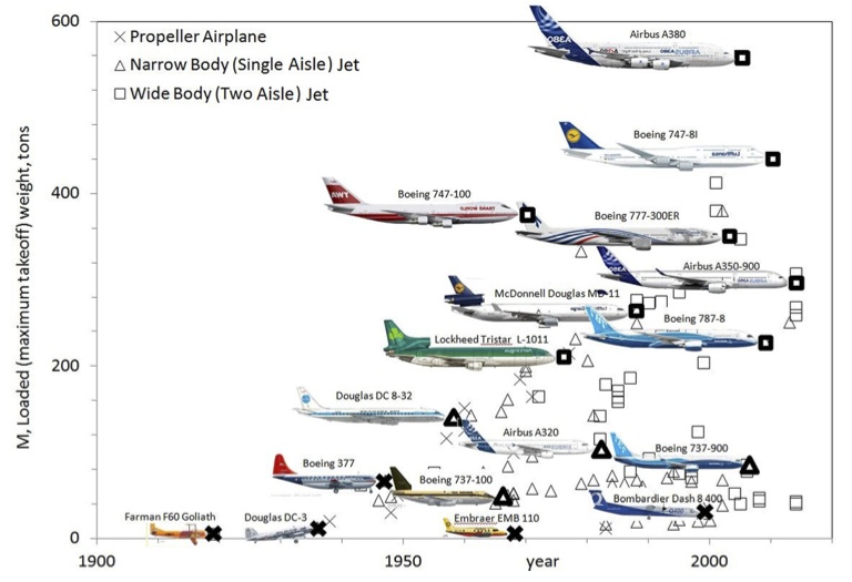
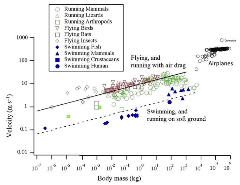
This overall trend is depicted nicely in Figure 1 which shows the size of new airplane models against the year they were put into service. It is evident that the biggest planes of one generation are surpassed by even bigger planes in the next. Based on economical arguments it can be assumed that each model introduced was in some way more efficient in terms of passenger capacity, speed, range, i.e. cost-effectiveness than the previous generation of the same size. Thus, in terms of the constructal law the spreading of flow is optimised and this appears to be closely matched with the airplane size and mass. Similarly, Figure 2 shows that both birds and aircraft evolve in the same way in that the bigger fly faster. Thus, the evolution of natural and technological designs seems to have converged on the same scaling rules. This convergent design is also evident in the number of new designs that appear over time. At the start of flight the skies were dominated by swarms of insects of very different design. These were followed by a smaller number of more specialised bird species and today by even fewer “aircraft species”. Combining these two ideas of size and number, it seems that the new are few and large, whereas the old are many and small.
Figure 1. Evolution of airplane mass versus time [2]Figure 2. Evolution of animal flight speed versus body mass [2]
The key question is why engines, fuel consumption or wing sizes should have a characteristic size?
Any vehicle that moves and consumes fuel to propel it depends on the function of specific organs, say the engines or fuel ducts, that interact with the the fuel. Because there is a finite size constraint for all these organs the vehicle performance is naturally constrained in two ways:
Resistance, i.e. friction and increasing entropy within the organs. This penalty reduces for larger organs as larger diameter fuel ducts have less flow resistance and larger engines encounter less local flow problems. Thus, larger is generally better
On the flip side the larger the organ the more fuel is required to move the whole vehicle. But the more fuel is added the more the overall mass is increased and the more fuel you need, and so on. This suggests that smaller is better.
From this simple conflict we can see that a size compromise needs to be reached, not too small and not too large, but just right for the particular vehicle. In essence what this boils down to is that larger organs are required on proportionally large vehicles and small organs on small vehicles. Thus, as more and more people intend to travel and move mass across the planet the old design based on small organs becomes imperfect and a more efficient, larger design for the new circumstances is required.
Overall, the researchers conclude that the physical principles of evolution define the viable shape of an aircraft. Thus, the fuselage and the wing must be slender, the fuselage cross-section needs to be round and the wing span must be proportional to the fuselage length. A famous outlier that broke with these evolutionary trends of previous successful airplanes was the Concorde with its long fuselage, massive engines and short wingspan. Rather than attempting to achieve an overall superior solution the designers attempted to maximise speed, and thereby compromised passenger capacity and fuel efficiency. Only 20 units were ever produced and due to lack of demand and safety concerns the Concorde was retired in 2003. Current aircraft evolution manifested in the Boeing 787 Dreamliner, 777X and Airbus A350 XWB are rather based on combining successful architectures of the past and with new concepts, that allow the overall design to remain within the optimal evolutionary constraints. Thus, it is no surprise that in an attempt to make aircraft larger and at the same time more efficient, the current shift from metal to carbon fibre construction is what is needed to elevate designs to a higher level.
The flight envelope of an aeroplane can be divided into two regimes. The first is rectilinear flight in a straight line, i.e. the aircraft does not accelerate normal to the direction of flight. The second is curvilinear flight, which, as the name suggests, involves flight in a curved path with acceleration normal to tangential flight path. Curvilinear flight is often known as manoeuvring and is of greater importance for structural design since the aerodynamic and inertial loads are much higher than in rectilinear flight.
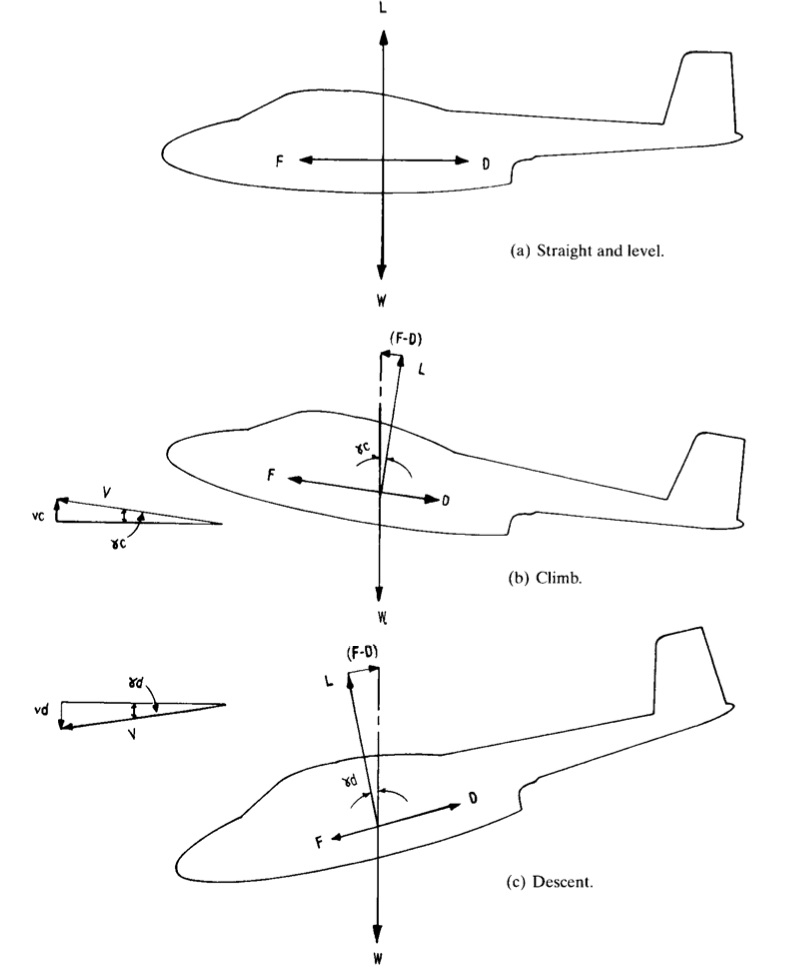
As the aircraft moves relative to the surrounding fluid a pressure field is set up over the entire aircraft, and not only over the wings, that acts to keep the aircraft afloat. This aerodynamic pressure always acts normal to the outer contour of the skin but the resultant force can be resolved into two forces acting tangential and normal to the direction of flight. The sum of the forces normal to the direction of flight give rise to the lift force L, which offsets the weight of the aircraft i.e. offsets the weight of the aircraft W. The tangential components give the resultant drag force D, which in powered flight must be overcome by the propulsive force F. The resultant force F includes the thrust generated by the engines, the induced drag of the propulsive system and the inclination of the line of thrust to the direction of flight. In basic mechanics the aircraft is simplified into a point coincident with the centre of gravity (CG) of the aircraft with all forces assumed to act through the centre of gravity. If the net resultant of a force is offset from the CG then a resultant moment will also act on the aircraft. For example, the lift generated by the wings is generally offset from the centre of gravity of the aircraft and may thus produce a net pitching moment that has to be offset by the control surfaces. Figure 1 below shows as a simplified free body diagram of an aircraft in level flight, climb and descent.
Fig. 1. Free body diagram of aircraft in flight (1)
Note that the lift is only equal and opposite to the weight in steady and level flight, thus:
[latex] F = D [/latex] and [latex] L = W [/latex]
In steady descent and steady climb the lift component is less than the weight, since only a component of the weight acts normal to the direction of flight and because by definition lift is always normal to both drag and thrust. Also in climbing the thrust must be greater than the drag to overcome the component of weight acting against the direction of flight and vice versa in descent. Thus in a climb:
[latex] L = W \cos \gamma_c [/latex] and [latex] F = D + W \sin \gamma_c [/latex]
and in descent
[latex ]L = W \cos \gamma_d [/latex], [latex] F = D – W \sin \gamma_d [/latex]
This situation is schematically represented in Figure 1 by the relative sizes of the different arrows. In general we can imagine the weight being balanced by the lift force L and the difference between the thrust F and the drag D. A bit of manipulation of the two equations for climb or descent above gives the same expression,
The latter expression is clearly obtained if Pythagoras’ rule is applied to the vector triangles that include (F-D) and L in Figure 1.
Figure 1 also shows velocity diagrams depicting the relationship between true air speed V, tangential to the direction of flight, and the rates of climb and descent [latex]v_c[/latex] and [latex] v_d[/latex] respectively. We can combine these velocity triangles with the forces triangles to obtain simple equations for the rates of climb and descent,
[latex] \sin \gamma_c = \frac{F-D}{W} [/latex] and [latex] \sin \gamma_c = \frac{v_c \ or \ v_d}{V} [/latex]
such that [latex] v_c [/latex] or [latex] v_d = \frac{F-D}{W} V [/latex].
This expression can also be used to gain some insight into the driving factors behind gliding flight. In this case the net propulsive force F is zero such that the expression becomes,
[latex] v_d = -\frac{D}{W} V [/latex] which may be approximated to [latex] v_d = -\frac{D}{L} V [/latex] since the angle of descent in gliding is typically very shallow. Therefore the gliding efficiency of a sailplane depends on maximising the lift to drag ratio L/D. If the ascending thermals are equal to or greater than this rate of descent than the glider can continuously maintain or even gain in altitude.
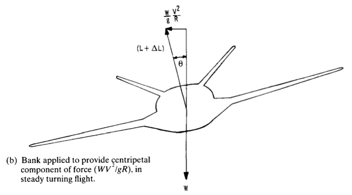
An aircraft may of course increase its speed along the direction of rectilinear flight in which case the thrust force F must be greater than the vector sum of the drag and the component of the weight. A more interesting scenario are accelerated flight where the acceleration occurs as a result in change in direction rather than a change in speed. By definition, in vector mechanics a change in direction is a change in velocity and therefore defined as acceleration, even if the magnitude of the speed does not change. A change in the flight path is achieved by changing the magnitude of the overall lift component or by differences in lift between the two wings, away from the equilibrium condition depicted in Figure 1. This change can either be obtained by a change in true airspeed or by changing the angle of attack of the wings relative to the airflow. Consider the simple banked turn in Figure 2 below.
Fig. 2. Free Body Diagram of an aircraft in a banked turn (1)
As the aircraft banks the lift force normal to the wings is turned through an angle [latex] \theta [/latex] from the vertical weight vector. Since the centripetal acceleration acts horizontally and the weight acts vertically we can use simple trigonometric relations to find the radius of turn:
[latex] \tan \theta = \frac{F_{centripetal}}{W} = \frac{m V^2 / R }{m g} [/latex] such that [latex] R = \frac{V^2}{g \tan \theta} [/latex]. It is also obvious that the more steeply banked the turn the more lift will be required from the wings since,
[latex] L = \frac{W}{\cos \theta}[/latex]
such that increase in engine power is needed to maintain constant speed under this flight condition. This is one of the reasons why fighter jets that require manoeuvres with very tight radii have such short and stubby wings. Small radii if turn R and thus high banking angles [latex] \theta [/latex] require increases in lift and therefore increase the bending moments acting on the wings.
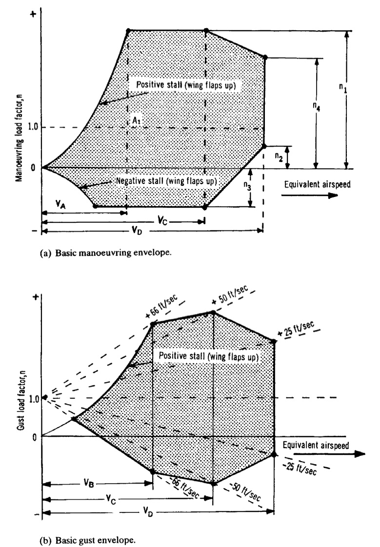
In reality the airplane is subjected to a large variety of different combinations of accelerations (rolls, pull-ups, push-overs, spinning, stalling , gusts etc.) at different velocities and altitudes. In classical mechanics free fall is expressed as having an acceleration 0f -1g and level flight is denoted as 0g. The aeronautical engineer differs from this convention in order to make the comparison between lift and weight simpler. This means that free fall is denoted by 0g and level flight by 1g. The ratio between lift and aircraft weight is called the load factor n, where [latex] n = \frac{L}{W} [/latex], i.e. n = 0 for free fall, n = 1 for level flight, n > 1 to pull out of a dive and n < 1 to pull out of a climb. The overall load spectrum of an aircraft is captured graphically by so called velocity – load factor (V-n) curves. The outline of these diagrams are given by the possible combinations of load factor and velocity than an aircraft will be expected to cope with. For example Figure 3a shows the basic V-n diagram for symmetric flight (asymmetric envelopes exist for rolls etc. but are not covered here).
Fig. 2 The a) basic manoeuvre and b) gust flight envelopes (1)
The envelope is constructed from the positive and negative stall lines which indicate, respectively, the maximum and minimum load that can be achieved because of the inability of the aircraft to produce any more lift. Thus,
[latex] L = n W = \frac{1}{2}C_{L_{max}} \rho V^2 S [/latex]
where [latex] \rho [/latex] is the density of the surrounding air and [latex] S [/latex] is the wing surface area. The limiting factor [latex] n_l [/latex] also known as the maximum expected service load is defined by
[latex] n_l = 2.1 + \frac{24 000}{W + 10 000} [/latex] or 2.5, whichever is greater, with W the max take-off weight.
[latex] V_A [/latex], [latex] V_C [/latex] and [latex] V_D [/latex] are defined as the maximum manoeuvre speed ( the speed above which it is unwise to make full application of any single flight control), the design cruise speed and the maximum dive speed, respectively. The intersection between the horizontal line [latex] n = 1 [/latex] and the left curve of the envelope is also of special significance since it represents the stall speed at level flight. In general the limit load factor must be tolerable without detrimental permanent deformation. The aircraft must also support an ultimate load (=limit load x safety factor) for at least 3 seconds. The safety factor is generally taken to be 1.5.
Finally, Figure 3b shows a typical gust envelope. A gust alters the angle of attack of the lifting surfaces by an amount equal to [latex] \tan^{-1} (w/V) [/latex] where w is the vertical gust velocity. Since the lift scales with the angle of attack up to the point of aerodynamic stall, the inertia forces applied to structure are altered by the gust winds. The gust envelope is constructed with the same stall lines as the basic manoeuvre envelope and different gust lines are drawn radiating from n = 1 at V = 0. Note that the design gust intensities reduce as the velocity increases, with the intention that the aircraft is flown accordingly. In the gust envelope [latex] V_A [/latex] is replaced with [latex] V_B [/latex], representing the design speed at maximum gust intensity.
References
(1) Stinton, D. The Anatomy of the Airplane. 2nd Edition. Blackwell Science Ltd. (1998).
As I described in a previous post, the efficiency of the gas turbine cycle increases as the turbine entry temperature (TET) is increased. Therefore the hotter the combustion gases that enter the first turbine stage the more specific power the jet engine can produce. Of course the TET is bounded by the metallurgical limits of the blade materials, specifically the blade root stress, the creep strain and the melting point of the blade material. The centrifugal stresses at the root increase linearly with the density of the blade material, and linearly with both the square of the rotational speed and the square of the ratio of root-to-tip radius. Creep is the continual and gradual extension of a material under constant load over time. Apart from distorting the physical dimensions and thereby reducing performance of the engine, the induced creep stresses exacerbate the centrifugal operating stresses and will therefore lead to premature failure of the material. A rule of thumb is that the blade life is halved (for a specific blade material and cooling technology) for each 10°C rise in temperature of the metal [1]. The TET has risen from about 1050K in 1944 to about 1750 in the 1994 Rolls-Royce Trent engine. This is partially due to the use of better materials such as Inconel and single-crystal metals with better creep and fatigue properties. However there is a bound to this solution since these nickel-based alloys are typically quite heavy, leading to an increase in centrifugal stresses at the root. Therefore more important in this development has been the technology of channelling of cold compressor air to cool the turbine blades. Using these advanced cooling techniques has allowed engineers to increase the TET beyond the melting point of the blade materials.
In a modern engine around 20% of the compressed air is bled off for cooling and sealing purposes for nozzle guide vanes and turbine blades [1]. This internal air system illustrated in Fig. 1 is also used to prevent the any hot mainstream gases from flowing over the heavily stressed blade-attachment discs and control tip clearances between turbine blades and casing. The stators and outer wall of the turbine flow passage use cooling air traveling from the compressor between the combustor and outer engine casing. The turbine rotor blades, disks and inner walls of the turbine flow passage use air bled from the compressor through inner passageways. Since the stators (or nozzle guide vanes) appear before the the first row of rotating blades, the first stage of stators are exposed to the highest temperatures, including local hot-spots from the combustor close by. The temperature at the first rotor stage is then somewhat decreased by dilution of the gases with cooling air, relative velocity effects and power extraction (by gas expansion causing a drop in temperature) from the turbine. In this manner the temperature reduces through each blade row.
Fig. 1. Detailed turbine cooling paths for stator and rotor stages [2]
The laws of thermodynamics require that due to combustion inefficiencies there be a pressure loss within the combustor. This means that the mainstream pressure at the first row of stators in the turbine directly after the combustor be lower than at the exit of the final stage of the compressor. It is this pressure difference that we use to drive the cooling air through the internal passageways and into the stators and blades. In this respect improvements in combustor design over the last years has been both an advantage and a disadvantage for cooling engineers. Improvements in combustor design has led to lower pressure losses within the compressor such that more force is available to drive the bled air to the hotter aft parts of the engine. On the other hand, with increasing compression ratios the air within the compressor naturally reaches higher exit temperatures (today around 900K !!! prior to combustion [1]) reducing the effect that the cooling air has on the turbine blades. Furthermore, the cooling air is expensive from an efficiency point of view since work has been done on the compressed fluid and we would ideally like to “waste” as little as possible for secondary cooling purposes. As in most case a compromise has to be struck between power output and turbine life.
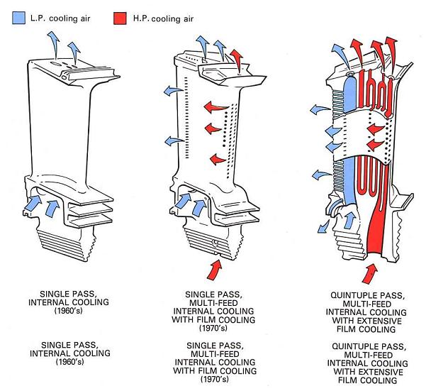
Fig. 2. Evolution of turbine blade cooling technology [3]
Figure 2 illustrates the evolution of turbine blade cooling over the last decades. In the early days of the jet era convection cooling was extensively used where the rotating blade acts as a single-pass cross-flow heat exchanger. This means that the bled compressed air flows radially through cooling passages in one-direction from root to tip, driven by the pressure differences and centrifugal forces, thereby removing heat convected to the blade from mainstream gases from axially. Improvements in modern manufacturing technology means that it is now possible to create a serpentine labyrinth of cooling passages within the blade turning the system into a multi-pass heat exchanger with higher cooling capabilities. Typically these passageways also have internal ribs and fins to increase the internal whetted area available for cooling. Furthermore, the cooling air is also vented through tiny holes onto the blade aerofoil surface, especially near the leading edge. In the ideal case the cooling air emerges at low velocity, forming a protective cooling film around the blade, hence the name film cooling.
The general cooling principles outlined above can be extended and combined to different cooling techniques. Some research has been conducted on exotic techniques for turbine discs as using pre-swirl nozzles to swirl the cooling air in the direction of the rotating discs. The increase in kinetic energy reduces the effective temperature of the air when it enters the cooling ducts in the blades. However the flow and heat structures that arise in these systems give rise to complex centripetal and Coriolis accelerations leading to accelerations in excess of 10,000g ! [1] with cyclonic and anti-cyclonic currents that are very difficult to model accurately.