Marc Ausman is the co-founder and CEO of Airflow, a California-based startup that is building an electric short-haul cargo aircraft. Marc holds a commercial pilot license, and among other endeavours, was previously the Chief Strategist for Airbus’ all-electric, tilt-wing vehicle demonstrator known as Vahana. Alongside four other former Vahana team members, Marc and the team at Airflow are building an aerial logistics network to move short-haul cargo quickly and cost effectively by using unused airspace around cities.
Key to Airflow’s vision is electric short takeoff and landing (eSTOL). Airflow’s eSTOL aircraft require only a few hundred feet for takeoff and landing—about the length of a football field—which means that runways can be built almost anywhere, even under existing regulations. What is more, even larger rooftops that can fit more than three conventional helipads could feasibly be used as a runway. Given the aerodynamic efficiency advantages of fixed-wing aircraft over rotary vertical take-off and landing (VTOL) aircraft, Airflow have come-up with an interesting alternative concept to many other companies in the growing urban mobility sector.
So in this episode of the Aerospace Engineering Podcast, Marc and I talk about:
Airflow’s vision of building the urban logistics network of the future
some of the misconceptions of eSTOL and eVTOL
the advantages of electric powertrains beyond reducing emissions
the technology Airflow is developing and challenges that need to be overcome
and striking a balance between financial and engineering incentives
On this episode I am speaking to Luca Leone who is the Head of Programme of AERALIS, a British startup designing a new class of military trainer and aerobatic jet aircraft. AERALIS have set out to re-invigorate the UK aircraft manufacturing sector with a military trainer that provides an exceptional pilot training experience.
AERALIS’ design is purposely modular meaning that a basic and an advanced version of the training aircraft are based on one common platform. This reduces costs in engine and airframe maintenance through training and spares commonality and also facilitates a shorter training period for pilots due to similarities between aircraft types. What’s more, AERALIS are developing a fully tailorable flying training system based on configurable cockpits and advanced simulators. In this way, AERALIS aim to not just be an aircraft manufacturer but a company that designs the total flying training experience. In this episode, Luca and I talk about:
the features of the basic and advanced trainer aircraft
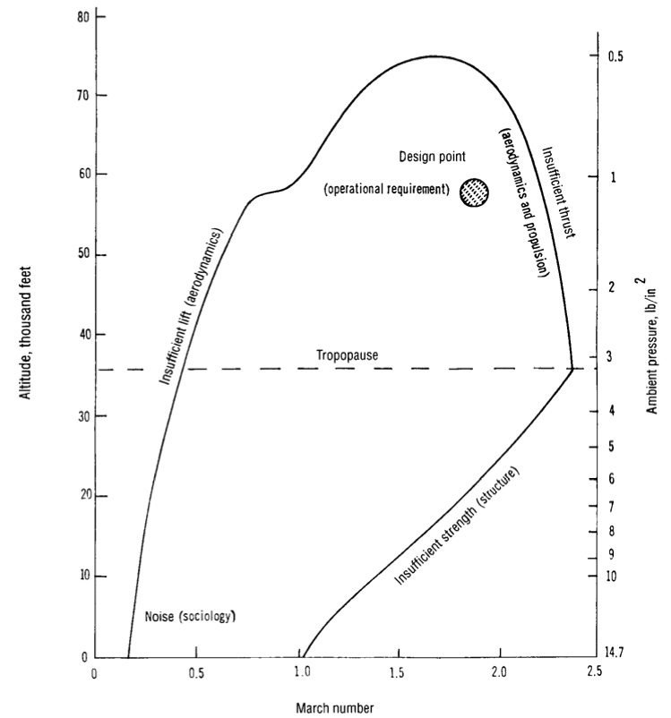
Every aircraft has a certain operational environment, including aspects of flight and ground operations, that it is designed to serve in throughout its lifetime. For example the operational requirements of a fighter jet are much more strenuous than those of a commercial airliner. The flight regime is broadly defined by the range of different flight speeds and altitudes called the flight envelope. Within this range lies the so-called design point, which is the operational environment in which the aircraft is expected to spend most of its time in. An example plot of a typical flight envelope is shown in Figure 1. The outline of the envelope defines the limit of performance for a specific aircraft configuration. The left edge defines the minimum speed required to keep the aircraft flying at a certain altitude. The small dip in the curve at around Mach 1.0 denotes the increase in drag caused by small supersonic pockets close to the leading edge of the airfoil. Supersonic flow is inherently terminated by a shock wave that causes an increase in fluid pressure. At speeds around Mach 1.0 these shockwaves are still located on the airfoil surface and therefore exacerbate the adverse pressure gradient across the suction surface, leading to premature boundary layer separation and higher pressure drag. The top of the curve marks the region where the minimum level speed is equal to the maximum speed that can be sustained by the aircraft’s engine and structural capability. The declining curve on the right indicates the envelope where speed is limited first by the power of the engines and then by the weight of the aircraft i.e. as the aircraft speed increases so do the loads on the airframe and therefore the material required (mass) to sustain these loads. The flight envelope in Figure 1 can be drawn for any aircraft and will be different depending on the unique role e.g. commercial transport, freight, fighter, bomber etc. Today the different roles of aircraft are no longer as clear-cut since aircraft are expected to fulfil multiple roles (e.g. freight and commercial transport) for economic reasons.
Figure 1. Flight envelope of supersonic aircraft (1)
The operating environment influences the overall shape of the aircraft which can broadly be broken down into three design segments: aerodynamic shape of wings, fuselage and controlling surfaces; the choice of propulsion; and the structural layout. Naturally, for a given design point and payload there will be conflicting requirements and optimal solutions for each area individually. However, an important point to realise is that an aircraft design will only be successful if these three design factors are dealt with concurrently i.e. the optimal compromise must be found.
The commutative property is valid for the above equation i.e. the shape of the aircraft is defined by the operational requirements, similarly the shape given to an aircraft restricts the functions that the aeroplane is capable of. This means that in the early parts of the design process the engineers need to be aware what variables can be fixed and where flexibility can be maintained to limit limitations if the design environment changes.
This picture is often complicated by a additional demands that have nothing to do with the flight envelope. Thus under the given flight envelope the engineers deal with added issues of economic requirements, manufacturability, passenger ergonomics and safety, airfield requirements, environmental and noise regulation. For example, an airline operator wishes to maximise profit on each flight and therefore a major incentive for commercial aircraft manufacturers’ is to cater to this need and not the goal of engineering state-of-the-art technology. Freight and travel airlines are in the business of making money from the payload they transport from A to B. The higher the profit per kg of payload carrier the better for the airline. In this respect the dry mass of the aircraft is of critical importance for profitability. The lower the dry mass of the airline the more payload can be carried over a certain distance for a given amount of fuel. Thus not only is the fuel efficiency improved (lower costs) but the revenue is also increased by carrying more goods. This is one of the reasons why lightweight composite materials are such a big driver for future aircraft design.
References
(1) Stinton, D. The Anatomy of the Airplane. 2nd Edition. Blackwell Science Ltd. (1998).