Every aircraft has a certain operational environment, including aspects of flight and ground operations, that it is designed to serve in throughout its lifetime. For example the operational requirements of a fighter jet are much more strenuous than those of a commercial airliner. The flight regime is broadly defined by the range of different flight speeds and altitudes called the flight envelope. Within this range lies the so-called design point, which is the operational environment in which the aircraft is expected to spend most of its time in. An example plot of a typical flight envelope is shown in Figure 1. The outline of the envelope defines the limit of performance for a specific aircraft configuration. The left edge defines the minimum speed required to keep the aircraft flying at a certain altitude. The small dip in the curve at around Mach 1.0 denotes the increase in drag caused by small supersonic pockets close to the leading edge of the airfoil. Supersonic flow is inherently terminated by a shock wave that causes an increase in fluid pressure. At speeds around Mach 1.0 these shockwaves are still located on the airfoil surface and therefore exacerbate the adverse pressure gradient across the suction surface, leading to premature boundary layer separation and higher pressure drag. The top of the curve marks the region where the minimum level speed is equal to the maximum speed that can be sustained by the aircraft’s engine and structural capability. The declining curve on the right indicates the envelope where speed is limited first by the power of the engines and then by the weight of the aircraft i.e. as the aircraft speed increases so do the loads on the airframe and therefore the material required (mass) to sustain these loads. The flight envelope in Figure 1 can be drawn for any aircraft and will be different depending on the unique role e.g. commercial transport, freight, fighter, bomber etc. Today the different roles of aircraft are no longer as clear-cut since aircraft are expected to fulfil multiple roles (e.g. freight and commercial transport) for economic reasons.
Figure 1. Flight envelope of supersonic aircraft (1)
The operating environment influences the overall shape of the aircraft which can broadly be broken down into three design segments: aerodynamic shape of wings, fuselage and controlling surfaces; the choice of propulsion; and the structural layout. Naturally, for a given design point and payload there will be conflicting requirements and optimal solutions for each area individually. However, an important point to realise is that an aircraft design will only be successful if these three design factors are dealt with concurrently i.e. the optimal compromise must be found.
The commutative property is valid for the above equation i.e. the shape of the aircraft is defined by the operational requirements, similarly the shape given to an aircraft restricts the functions that the aeroplane is capable of. This means that in the early parts of the design process the engineers need to be aware what variables can be fixed and where flexibility can be maintained to limit limitations if the design environment changes.
This picture is often complicated by a additional demands that have nothing to do with the flight envelope. Thus under the given flight envelope the engineers deal with added issues of economic requirements, manufacturability, passenger ergonomics and safety, airfield requirements, environmental and noise regulation. For example, an airline operator wishes to maximise profit on each flight and therefore a major incentive for commercial aircraft manufacturers’ is to cater to this need and not the goal of engineering state-of-the-art technology. Freight and travel airlines are in the business of making money from the payload they transport from A to B. The higher the profit per kg of payload carrier the better for the airline. In this respect the dry mass of the aircraft is of critical importance for profitability. The lower the dry mass of the airline the more payload can be carried over a certain distance for a given amount of fuel. Thus not only is the fuel efficiency improved (lower costs) but the revenue is also increased by carrying more goods. This is one of the reasons why lightweight composite materials are such a big driver for future aircraft design.
References
(1) Stinton, D. The Anatomy of the Airplane. 2nd Edition. Blackwell Science Ltd. (1998).
The treatment of defects in aircraft structural design has been an important aspect in aircraft structural design during the last 50 years. Various different catastrophic events have led to key insights that now shape the design philosophy for primary aircraft structures. One of these is the distinction between Safe-Life and Fail-Safe structures. Safe-Life components are designed to go through their service life without cracks and defects playing a major role in the stress state of the component. Thus, the required fatigue life to initiate a crack is kept below the anticipated service life. This design approach is mainly used for components for which there are no back-ups in place and where failure would lead to the loss of the aircraft. A typical example of a Safe-Life component is the landing gear and this remains one of the reasons why landing gears are made from high-strength steel for which engineers have a long history of structural data. The second “Fail-Safe” design philosophy assumes that any real manufacturing process will induce defects within the part that, even if microscopic, may vary between different batches and may grow during the service life. Thus the Fail-Safe components are structurally designed to withstand all imposed loads up to a certain certain level of defect, known as the “critical size”, which can usually be detected by eye and act as stress concentrators. In this manner critical components are continuously monitored at specific service intervals to make sure that no crack exceeds the critical defect size, and is subsequently replaced if this happens. Furthermore, crack propagation analyses are employed in order to ascertain how many flights/load cycles it will take to grow a crack to the critical size. Most of these insights stem from the experience engineers have gained during the last 50 years with metal aircraft and in fact there was quite a steep learning curve during the transition years from wood to metal aircraft.
Today we are facing a similar transition from metal to mostly fibre reinforced plastics and other advanced materials whose failure mechanisms are often much more complex than that of metals. First, in metallic structures a crack typically initiates at an imperfection or stress concentration and then propagates under fatigue loading until final failure. The damage morphology in composites however is completely different: a large number of microscopic defects, such as micro-cracks that occur during post-cure shrinkage of the resin are present over a large volume of the material and these may develop into different failure mechanism over time. Second, most metals have a ductile failure mechanism such that overloading can visually be detected by the onset of plastic deformation. Therefore there is often a warning period between a structure being overloaded and failing catastrophically. Fibre reinforced plastics, especially carbon fibre composites on the hand fail by more brittle and therefore sudden mechanisms. Third, while a major driver of component design for metal structures is crack growth, which can be predicted quite accurately today using analytical methods or Finite Element codes, fibre reinforced plastics have a plethora of other failure mechanisms and manufacturing defects that are equally important. Some examples are fibre breakage, matrix cracks, matrix-fibre debonding, delaminations, voidage, misplacement of plies, lack of impregnation and fibre waviness. Interlaminar failures such as delaminations are especially important since they can occur very quickly when a laminate is loaded through the thickness, for example at stringer run-outs, in corner-radii of C-spars or simple impact events such as tool drop in the factory. Since there are typically no reinforcing fibres in the perpendicular direction the structural integrity is only guaranteed by the weak matrix. Due to this inherent weakness different plies may literally be pulled apart at their lamination interfaces. Techniques such as through thickness reinforced such as 3D braiding, Z-Pinning or nano-fibre reinforcement are currently being researched. Under compressive forces these delaminations may form blisters, so called delimitation buckling, which can easily propagate along the lamination interface leading to disintegration of the part.
Fig. 1 Delamination Buckling in Composite Laminate
Finally, different failure mechanisms actually interact making accurate predictions of the failure load including a defect extremely difficult. Furthermore, even experimental data for laboratory sized specimens cannot readily be used for real-sized components since the scaling up of structures has been found to greatly alter the dominant failure mechanism. Finally, failure sites in fibre reinforced plastics are often internal meaning that an engineer will not be able to detect them by simple visual investigation during service intervals. As a result, the increasing use of fibre reinforced plastic construction during the recent years and near future means more sophisticated evaluation techniques are required for guaranteeing safe design and operation of aircraft. Another key question is how these new types of defects can be taken into account reliably in structural design?
Compared to metallic materials composites have a very unique characteristic in that the material and structure/part are created simultaneously. This means that the amount of imperfections in the part is greatly dependent on the manufacturing process. In composite materials the fail-safe design philosophy of degrading the material properties to that including a “critical defect size” is not only important to reduce the probability of failure as in metallic structures but also because a manufacturing process free from imperfections would be financially prohibitive. Thus, the degree of process and quality control depends greatly on the safety requirements of the industry. For example, the high-volume and competitive automobile sector needs to guarantee passenger safety while keeping manufacturing costs at a minimum. In the aerospace industry however the mass of components is absolutely critical and takes precedence over the manufacturing costs. As a result the automobile industry relies more on out-of-autoclave infusion processes that allow high production volumes such as Resin Transfer Moulding, while the aerospace industry currently relies on the high-temperature, high-pressure curing environments of the autoclave that allow the manufacture of high performance parts with low, controlled level of imperfections.
Non-destructive testing (NDT) methods are often employed to detect defects inside or on the surface of a material. In general they are broken down into surface methods, bulk volume methods and global methods. These methods are typically used at the end of the manufacturing process as a quality control measure or during the life of the part to monitor and assess its fitness for continuing use. Surface methods include visual inspection techniques such as scanning the surface for obvious cracks, porosities, resin rich/starved regions or surface waviness. This is often coupled with endoscopes to examine remote or difficult to access locations. Furthermore a common technique is dye penetrant inspection where a dye is applied to external surfaces and illuminated with an ultraviolet light in order to highlight cracks on the surface that the dye has crept into. This technique was quite popular for aero engine components but is inherently quite time and labour intensive.
1. Section of material with a surface-breaking crack that is not visible to the naked eye. 2. Penetrant is applied to the surface. 3. Excess penetrant is removed. 4. Developer is applied, rendering the crack visible. (1)
Bulk volume methods range from the simple tap test to ultrasonic screening to the most sophisticated X-ray and computer tomography techniques. The choice of the method depends greatly on the type of defect that is to be detected and criticality of cycle time and production costs. Simple surface defects, core crush in sandwich structures may easily be detected using visual techniques, while tap tests can be used very effectively to determine delaminations or large internal voids. In a tap test the component is tapped lightly with a hard object such as a coin or ring which emits a very dull sound if a delimitation lies beneath the testing point. On the other hand the exact location and size of a delimitation, possible contaminations, voids or micro-porosities can only be detected with ultra-sonic or C.T. techniques. In this respect ultra-sonic scanning has developed to be the most widely-used NDT technique in the aerospace industry due to its high detection fidelity, compactness and relative low-cost compared to C.T. techniques. In ultra-sonic scanning ultrasound is projected into a component and by measuring the strength and time delay of the echo it is possible to detect inclusions (air, solid objects etc.) that differ from the host composite material.
Fig. 3. Principle of ultrasonic testing. LEFT: A probe sends a sound wave into a test material. There are two indications, one from the initial pulse of the probe, and the second due to the back wall echo. RIGHT: A defect creates a third indication and simultaneously reduces the amplitude of the back wall indication. (2)
One of the drawbacks of ultrasonic scanning is that some sort of coupling agent (typically water or a gel) is required between the probe and surface of the part to guarantee a high-quality reading. Furthermore, the scanning of large areas can be very time intensive even with the use of multi-probe ultrasonic arrays that can be rolled across a surface or controlled by a robotic arm, such that this technique is typically restricted to critical or highly-stressed components. Finally, CT techniques are currently only widely used in academia where they can give very useful insight into the exact 3D morphology of a cured part and show how and where cracks are initiated and when they propagate. Some pieces of equipment like Synchrotron radiation computed tomography at the University of Southampton can produce extremely detailed 3D plots and videos of parts under load that are very useful to help researchers understand what drives failure in composite materials.
Fig. 4. 3D Synchrotron Image (3)
Finally, in recent years global methods such as structural health monitoring have been a hot research topic. In structural health monitoring sensors such as strain gauges or fibre-bragg grating systems are embedded within the structure and provide real time data on the stress state. In this manner the health of the structure can be monitored in real time and service intervals and replacement parts be installed at the required times. However, these systems can probably not be embedded throughout an entire aircraft and require an incredible amount of storage to cope with the continual data stream.
Understanding the detrimental effects of imperfections and the damage mechanisms is essential in order to take full advantage of the benefits that high performance composites have to offer. In this respect non-destructive testing is a very valuable tool for investigating and mapping the internal condition of a component. One of the challenges facing the aerospace and automobile industries in the future is deciding what detail of non-destructive testing is required to guarantee the structural integrity of the products to a high degree of probability during the entirety of its service life and balancing this against the cost that the specific techniques incur.
I have just returned from the International Conference for Composite Materials (ICCM) in Montreal, Canada and would like to share a few observations and key points about the developments in the composite world that may not be so easily accessible to a broader audience.
1) The Great Advance – Applications
ICCM is the biggest conference for composite materials and this year united over 1500 delegates from academia and different industrial representatives from the classical sectors aerospace, wind energy and high performance cars to newer sectors such as mass market cars (e.g. BMW i3), biomedical applications and even musical instruments. The motto of the conference “Composite Materials: The Great Advance” aptly captures the current state of technology in the industry. Since the 1960 considerable amount of research has been conducted to elucidate the mechanical and chemical properties of the fibre material, matrix and cured composite under various conditions such that the global behaviour of these materials is now sufficiently characterised. This maturity in technology coupled with the ever decreasing costs and the inherent benefits of high specific stiffness and strength that fibre-reinforced plastics have to offer, has led to the increasing application of composite materials in very different industries that we see today. Thus the “great advance” of composite materials towards wide-spread use in many industrial sectors.
Fig. 1. Composite materials growth broken down by sectors (1)
Fig. 2. Carbon Fibre Market (2)
2) The Great Advance – Novel Technologies
Furthermore, “The Great Advance” also relates to novel composite materials with much greater complexity that blur the lines between what is a material and what is a structure. Of course on a macroscopic scale one could say the steel in a steel bridge is the “material” that has been used to construct the “structure” that is the bridge. Therefore in this classical interpretation steel is just the building block to make the bridge, while the structure itself is the final product that performs a function. However on a microscopic scale we could argue that steel is a structure in itself since it is “constructed” of different sized grains that contain different metallic compounds and is thus an arrangement of small particles i.e. a microstructure. We could of course continue this argument further and further up to the atomic scale at which point we have reached the field of nanotechnology. This field of research has enjoyed much popularity in recent years since by manufacturing our products from the ground-up, i.e. from the nanoscale to the macroscale, we can control the properties of our product at multiple length-scales and therefore tailor the characteristics to be optimal for the desired function in service or even add some sort of multi-functionality to the structure/material. Since the material and structure are built at the same time the dividing line that used to distinguish between these two concepts is blurred. Even for a simple composite laminate comprised of a stack of individual layers this divide is no longer so clear since we can define the properties of each ply in the stacking direction and therefore have control over one more length scale.
Therefore in the future there will be a great advance towards novel and multifunctional materials/structures that perform so much more than carrying structural loads. Currently the design of composite structures is still in some cases dominated by a “black aluminium” approach. That is taking the current designs that have worked so well over the last decades using aluminium and replacing them by an equivalent composite design. The problem with this is that on one hand the composite material may not be suitable to carry loads in the same configuration e.g. loads through the thickness have to be avoided to prevent delaminations. Most importantly however, such a design approach hinders the greatest advantage of this new material system, which is to facilitate entirely new structures in terms of functionality and shape that arise as a results of their inherent properties. Only by completely re-designing structures from the ground-up and taking the intricacies of this new material system into consideration can we arrive a new optimal solutions or conversely ascertain that a metal solution actually works better under some circumstances. In the following I want to share a few exciting technologies that you may see in the near future.
1) Variable stiffness technology
This is my field of research and essentially what we are currently doing is changing the fibre direction over the planform of the plate such that we have curvilinear fibres rather than the straight fibre laminates that we use today. In many aerospace applications we require different laminate stacking sequences in different parts of the structure. Abruptly changing from one stacking sequence to another can lead to stress concentrations and thus structurally weaker areas at the interface. Using the variable fibre concept we can easily spatially blend from one layup to another to reduce these problems. Furthermore, we can arrange the fibre paths to follow the dominant load paths as for example around a window in an aircraft fuselage. Loads in a structure always follow the path of highest stiffness. So by aligning the fibres in the load direction in supported areas of the laminate (for example the vertical edges in Fig. 3 below if the load is applied vertically onto the horizontal edges), a large portion of the stress can be removed from the unsupported centre of the panel, which can greatly improve the elastic stability of the structure. This has great potential for future wing structures since the design of wing skins is greatly governed by local buckling (Fig. 4). It has been shown that the buckling loads can be improved by 70%-100% using variable stiffness technology (5), thus the possibility exists to reduce the weight of wing structures by up to 20% using this technology.
Fig. 3. A variable angle tow laminates (3)
Fig. 4. Buckling analysis of a stiffened wing panel. The stiffeners break the buckling mode shapes into smaller wavelengths that require higher energy to form than a single wave (4)
Another form of various stiffness technology is placing material in areas where it is needed and removing it from areas where it is not required. Nature is an expert in achieving this and many of our current design are based on bio-mimicry. For example, your bones are continuously being re-modelled based on the stresses that are placed on your skeleton. In this way the density of your bones is increased in highly-stresses areas and decreased in areas that are not used so much. In the same way sea-sponge arranges its structure in a way to achieve the most efficient design. Similarly, wood possesses an incredibly complex microstructure that is composed of different structural hierarchies at different length scales. This is similar to a rope where individual fibres are twisted together to make strands, strands are twisted together to make bundles, and bundles twisted together to make the complete rope. This approach of designing at multiple length-scales makes wood very ductile and resilient to cracks. In this manner attempts have been made to reproduce such a hierarchical design by arranging short fibres using standing ultrasonic waves.
Fig. 5. Microstructure of wood. Notice the different structures at different length scales that gives wood its inherent strength (6).
2) Self Healing
Yes, materials can heal themselves. The most popular example is that of self-healing asphalt, which was presented a few years ago at a TED conference. In terms of composites 100% recuperation of mechanical properties have been achieved when the mode of failure has been dominated by matrix cracks. In high performance composites the matrix is currently some sort of thermoset or thermoplastic, which allows vascules of uncured resin to be included in the structure which may break open as a crack propagates. The uncured resin then permeates through the open crack and cures in-situ to repair the full functionality of the part. The dissemination of the healing process can also be achieved using very thin vascules that are arranged throughout the part. In this manner the structure starts to behave very much like a living organisms with the vascules serving as pathways for repair very similar to the veins in an organism. Recently, a great article by the BBC summarised the major achievements in this field.
Fig. 6. Self healing capsules (7)
Fig. 7. Self healing vascules (7)
3) Nanotechnology
Nanotechnology has been extremely popular during the last 20 years due to the fact that theoretical predictions promise incredible benefits for almost all applications in engineering. In terms of advanced composites however, there are still problems of evenly dispersing nanotubes in resins with agglomeration or alternatively producing continuous nano-strands at low costs. In the aerospace industry they show great promise in increasing the electrical conductivity of laminates to improve their resistance against lightning-strike, creating structures for magnetic shielding and providing interlaminar strengthening using nano-forests. One of the cooler things I saw at ICCM was research conducted on nano-muscles, which are essentially nano-fibres that have been twisted into a rope and can achieve very high actuation forces and strokes at very little mass.
4) Structural Batteries / Energy Harvesting
Solar power has incredible potential as an energy source since it is the largest form of energy available for consumption on earth and is limitless. However, solar power is sporadically dependent on the weather conditions, which makes energy conversion rather cost intensive and inefficient. However, solar energy harvesting might find increasing use if actively integrated into load-bearing components as a multi-functional structure. Bonding thin-film solar cells onto lightweight composites would eliminate the material redundancy of stand-alone supporting structures and could easily be integrated into current laminate manufacturing technology. Photovoltaic (PV) cells have been embedded in composite laminates and their performance has not been impeded by the curing process. However, the performance of the PV cells diminishes rapidly under static loading since the loading causes cracks in the cells. Similarly there are ideas to create structural batteries such that the load carrying chassis of a car can be “charged-up” to additionally serve as the battery for an electric powertrain. Of course this would have the great advantage that the heavy batteries used today could be eliminated to some extent. BAE systems are working on technology to embed battery chemistries into the carbon fibre fabric.
5) Morphing
Finally, morphing or shape-changing structures have been extensively studied since the 1970’s for providing aircraft with the possibility of adapting the shape of their wings to provide the optimal lift for different flight scenarios. Of course this is to some extent already used in aircraft with the aid of leading edge slats and trailing-edge flaps to increase the lift-coefficient for slower flight regimes such as landing and lift-off and in Formula 1 using drag reduction system of the rear wing. However, slats and flaps on an aircraft greatly increase the drag of the profile during deployment and increase the weight of the structure do the heavy actuation mechanism. Therefore the aim is to design an integral system such as the trailing-edge design shown below. Other examples of morphing structures include air intakes for cars, noise-reducing chevrons on jet-engines, or high-temperature composites used for jet-engine turbine blades that change there angle of attack based on the temperature of the airflow around them.
Fig. 8. A morphing trailing edge using a flexible honeycomb (8).
However, in most cases these technologies are very difficult to apply to primary aircraft structures. This is because there is a direct conflict between the high-stiffness, high-strength requirement for carrying loads and the low-stiffness, large-deflections required for shape-changes. Thus, a driver to facilitate these technologies will be the development of materials that change there mechanical properties under different circumstances.
3) The Great Advance – Solving “big” problems for larger scale implementation
Finally, one of themes during the conference was trying to solve some of the major problems faced by the industry hindering further implementation of current composite technology in all industrial sectors. Of course for some industries such as mass consumer automobiles the biggest barrier to entry is cost. The new BMW i3, which will enter the marketplace at the start of 2014, will cost £30,000+ and is therefore quite a big investment for a small city vehicle. Of course some of the cost can be attributed to the cost of the electrical drivetrain and batteries but other manufacturers such as Renault have shown that a lot of these costs can be reduced by employing a scheme based on renting batteries rather than buying them with the vehicle. In case of the i3 a lot of the extra cost is simply down to the fact that BMW are the first to build a mass produced automobile using a large amount of fibre-reinforced plastics in primary structural parts. Not only is cost of raw material much higher than for lightweight metals such as aluminium but the manufacturing processes and supply chain management required for reliable mass production were simply not in-place beforehand. Furthermore, a shift in design methodologies is required since the chemical and mechanical behaviour of composites is so different from the metal environment that the automobile industry is so used to dealing with. As an example, proving the structural integrity for the incredible rigorous crash/impact certification using rather brittle composite materials compared to more ductile metals is a challenge in itself. Thus, the relatively high price-tag of the i3 incorporates some of the research and development costs that BMW have had to face in developing composite technology for their market sector. No doubt the cost of mass market composite cars will reduce drastically in the next decade as the raw material price further reduces and design methodologies and manufacturing processes mature.
Another major issue hindering the implementation of composites especially in the aerospace industry is the difficulty of predicting the failure behaviour of these materials. On problem is the large number of failure modes that may occur: fibre breakage, matrix cracks, delamination, fibre crimping, fibre-matrix debonding, global and local buckling etc. and thus finding accurate failure loads for all these phenomena under different load cases. Since a larger number of these failure mechanisms originate on a local, micro-mechanical scale high-fidelity 3D Finite Element models are often needed to fully understand the mechanisms of failure and predict the load-carrying capability of different structures. Considering the size of any commercial aircraft it is absolutely inconceivable to apply such detailed and computationally expensive analysis tools to every part of an aircraft. Furthermore, the failure mechanisms are not as well defined as for metal materials. That is in classical tensile or compressive tests a specimen may undergo some form of non-linearity that may for a metal specimen be classified as a failure event but for the composite considerable residual strength is available. Conversely the failure behaviour of composites can be very brittle with very little warning compared to the gradual, ductile failure mechanism of most metals used in the aerospace industry. Considering the intricacies of composite failure modes and the fact that the individual failure modes may interact or even change in criticality depending on the size of the component and environment in which it is used, it is no wonder that currently very conservative safety factors are being employed for primary composite aircraft structures that greatly offset the weight-savings that are possible using this new material system. Thus, one of the biggest if not the biggest topic in composite structural design for the next couple of years will be the challenge of developing simple and yet robust failure criteria to be used for composite designers.
(5) Gürdal Z, Tatting B, Wu C. (2008). “Variable stiffness composite panels: Effects of stiffness variation on the in-plane and buckling response”. Composites: Part A, 39(5), pp. 911-922.
(6) Greil P, Lifka T, Kaindl, A. (1998). “Biomorphic Cellular Silicon Carbide Ceramics from Wood: I. Processing and Microstructure”. Journal of European Ceramic Society, 18(14), pp. 1961-1973.
(7) Rincon, P. (2012). “Time to heal: The material that heal themselves.”http://www.bbc.co.uk/news/science-environment-19781862
(8) Daynes S & Weaver P.M. (2011). “A Morphing Wind Turbine Blade Control Surface”. Proceedings of the ASME 2011 Conference on Smart Materials, Adaptive Structures and Intelligent Systems. Phoenix, AZ: ASME.
In this post I want to use the sandwich panel as an example to explain some basic concepts about bending of structures. The explanations in this post are kept very basic and are similar to a first semester course in structural mechanics. Sandwich panels are an important composite structure in aerospace applications as well as in high performance automobiles, boats and wind turbines. Typically a sandwich panel is comprised of a low stiffness, low density inner core enclosed by two stiff outer skins, as shown in Figure 1, where the whole assembly is held together by some sort of structural adhesive (Figure 2). The outer skins are typically made from stiff carbon fibre or aerospace grade aluminium.
Fig. 1. A honeycomb carbon fibre sandwich panel (1)Fig. 2. Sandwich panel components and construction
The inner core is typically a Nomex or metal honeycomb, or an open or closed cell foam. Nomex is an aramid polymer similar to Nylon that is flame-resistant and can be manufactured in paper sheet form. Nomex is a great choice for the interior of aircraft cabins such as the floor panels due to its high safety in the event of fire. Multiple sheets of Nomex paper can be placed on top of each other and glued together at the node locations by lines of adhesive, which are offset spatially between different layers. This large stack of Nomex can then be cut into smaller strips and expanded to form a sheet of Nomex honeycomb. Alternatively closed cell foams such as Rohacell® are commonly used for the core, which are denser then there open cell counterparts but prevent moisture ingress in service and have better mechanical properties.
Fig. 3. Manufacture of a honeycomb sheet (2)
But what is the advantage of using a sandwich panel?
Various structures on an aeroplane are subjected to bending loads. Essentially the bending of a beam or a plate, by say some sort of pressure loading over its surface, is equivalent to grabbing the edges and applying a moment or rotation. Under pure bending Engineer’s bending theory assumes that the structure resists this moment by a linear variation of stress through its thickness. Thus, the maximum stresses occur at the top and bottom surfaces, one being compressive and the other tensile, while the stress at the middle of the beam thickness is zero. This unstressed location is called the neutral axis. For pure bending the neutral axis is always located at the centroid of the cross-section (the mid-plane for a rectangular cross-section) and can be calculated using the integral expression for the first moment of area. Therefore we can see that that the structure balances the externally applied bending moment by an internal force couple of equal magnitude where the fulcrum of the couple is the location of the neutral axis.
Fig. 4. Bending moment and internal stress distribution of beam under pure bending (3)
However this linear variation of stress is not very efficient since the cross-section of the beam is not uniformly stressed i.e. it would be more efficient if the whole cross-section was constantly loaded by the average stress to spread out the load. One method to improve the design is to cut-out the material close to the neutral axis in order to reduce structural mass as shown in Figure 5. Another possibility is to use a sandwich panel i.e. place stronger material towards the outside where it is needed and replace the interior section with a less dense and therefore lighter (and generally weaker) material to save weight.
Fig. 5. Fuselage frame with flared holes (4)
A major advantage of the sandwich construction compared to the flared hole design is that the core separates the stiff outer skins, placing them as far as possible from the neutral axis. The degree in which a structure prevents deflection in bending is known as the bending rigidity EI, where E is the Young’s modulus or stiffness of the material used and I is the second moment of area. The second moment of area I, which is the bending resistance of the cross-section, increases the more mass is located away from the neutral axis. This is analogous to rotational motion where the inertia of rotation increases the further away the rotating mass is located from the centre of rotation. In fact, as the name “second moment of area” suggests, the bending resistance increases with the square of the distance from the neutral axis. Thus a sandwich panel moves two stiff skins (high values of E such as Carbon fibre laminates) far away from the central neutral axis in order to maximise the product EI and therefore create a structure of incredibly high specific flexural stiffness i.e. high bending stiffness coupled with minimum mass. The improvements of stiffness versus weight of a sandwich panel by increasing the separation of the two face sheets is clearly illustrated in Figure 6. Here the density of the face sheets is assumed to be 15 times higher than that of the core.
Fig. 6. Stiffness vs. weight comparison for a sandwich panel
Apart from increasing the bending rigidity another advantage of using sandwich panels is that it actually concentrates the direct bending stresses (axial and shear ) in the face sheets. This is because when a structure deforms the load always distributes relative to the stiffness of the different parts. For example, when two springs are aligned in parallel and fixed on one end by a support and are displaced by the same extension x on the other end the load taken by spring 1 will be twice as high as that by spring 2 if .
Fig. 7. Two springs in parallel (5)
This is equivalent what happens to in a sandwich beam. Since the face sheets have much higher Young’s modulii than the low-density core, in bending the large majority of the direct bending loads is actually taken by the face sheets. This means that the stress distribution is no longer continuously linear through the entire cross-section as for an isotropic material in Figure 4, but actually piecewise linear and discontinuous at the interfaces. For example Figure 8 below clearly indicates how the variation of stress through the thickness of the sandwich panel changes as the stiffness mismatch between the core and face sheets is increased. As the modulus of the skins reaches 50 times that of the core there is a large jump in bending stress from just over zero to about 2 MPa. Compared to the case of equal Young’s modulus this solution is much more efficient since both the skins and the core are more uniformly stressed. The limitation of this design is that the large discontinuity of bending stress at the interface may cause excessive transverse shear stresses at the interface that can literally pull the face skins away from the core and cause de-bonding of the two parts. This is why it is important to use a core with high transverse shear modulus and strength such as honeycomb to absorb these transverse shear loads. Furthermore, the core transverse shear strength is important for resisting point or distributed pressure loadings over the surface of the face sheets and give local support for fasteners.
Fig. 8. In-plane stress profile through the thickness of a sandwich panel for various ratios of core-to-face sheet Young’s modulus
Of course there are also many drawbacks of using sandwich panels. For example when using honeycomb cores it is very hard to form complex curved shapes using the standard hexagonal matrix shape. This is because honeycomb has very high values of Poisson’s ratio such that the anti-clastic curvature effects in bending are quite pronounced. This means that when the honeycomb is bent to adhere to a certain shape it will form opposite curvature in the perpendicular direction to form a saddle shape. During in service bending deformation this will also cause the centre of the core to want to pull away from the face sheets again leading to excessive transverse shear and normal stresses at the interface and possible de-bonding of the core and face sheets. In fact de-bonding may also occur due to impact events or slow moisture ingress into the open cell honeycomb structure during service. Furthermore, when not properly designed honeycomb cores may collapse under the external pressure loading when the sandwich panel is cured in the high-temperature and pressure oven known as an Autoclave. Some of these drawbacks can be overcome by using closed-cell forms such as Rohacell®, which have lower degrees of anti-clastic curvature and, being “closed-cell”, greatly reduce the danger of water ingress into the core. The drawback of these foams is that there intrinsic higher density makes them heavier than the equivalent honeycomb solution. Alternatively, different cellular core configurations other than honeycomb such as Flex-core, rectangular and square may be used to reduce the anti-clastic curvature problem.
Fig. 9. Different cellular core styles
In metal construction the analogy to the sandwich beam is the I-beam seen in many civil constructions. Here the two flanges are located away from the neutral axis by the vertical web section. The difference in this design is that the vertical web section does also take considerable direct in-plane loads since it is of the same material and therefore stiffness as the two flanges. However, I-beams are much more cost-effective than sandwich beams since they can be easily mass-produced and do not suffer difficulties such as debonding between the face sheets and the core.
In summary a sandwich comprises,
two stiff and lightweight face sheets that predominantly take in-plane stresses and shear loads
a low-density core that takes transverse shear loads, separates the face sheets for high bending rigidity, supports the face sheets against buckling modes forming and can give local support for fastener loads
an adhesive holding the entire assembly together which transfer shear loads to the core and keeps the skins in the correct location.
There is a saying that your audience will halve for every equation you put in a piece of writing. Well, in this case I am going to make an exception and go through the detailed derivation of the Breguet Range equation. The reason for doing this is that the maths is not very difficult but the implications of the equation are known to every pilot on earth and everyone interested in flight should know about it. Simply put, the Breguet range equation tells engineers how far and airplane can fly given a certain set of parameters, and therefore greatly influences the design of modern jet engines and airframes.
A central aspect of flying further for the same amount of fuel is maximising the lift to drag ratio of your wings and airframe. Optimising this ratio gives the maximum aircraft weight (=lift at steady horizontal flight) that can be kept in the air for a given amount of engine thrust (=drag at steady horizontal flight). However, this parameter is not the primary optimum for commercial flight. Instead one wants to fly the furthest possible distance with one fuel filling. Thus to achieve the maximum possible range the quantity to be optimised is the product of flight speed (U) with lift (L) to drag (D) ratio [latex]\frac{UL}{D}[/latex]. For most long-haul journeys (~12 hours) the most time consuming part of the journey, and therefore most critical for fuel consumption is the cruise condition. During cruise conditions the band of altitudes that the airliner travels through does not vary greatly such that the local speed of sound [latex]U_s=\sqrt{\gamma R T}[/latex] where T is the local static temperature, does not vary greatly. Consequently optimising the Mach Number [latex]M=\frac{U}{\sqrt{\gamma R T}}[/latex] times the lift to drag ratio [latex]\frac{ML}{D}[/latex] is virtually the same.
Figure 1 shows experimental data of this parameter versus the lift-coefficient [latex]C_L = \frac{2L}{\rho v^2 S}[/latex] for a Boeing 747-400 at 35,000 ft. At each Mach number L/D rises to a maximum until further increase in lift coefficient leads to stall of the aerofoil. At lower flight speeds the boundary layer separation will occur naturally towards the trailing edge but as we approach a flight speed of Mach 1 shock waves also come into play. The graph shows that for all cruise speeds the optimum value of [latex]\frac{ML}{D}[/latex] occurs at a lift coefficient of about 0.5. The wing area S of an aeroplane is set largely by conditions at take-off and landing, such that it is hard to continually operate at a lift coefficient of 0.5 as the weight and therefore lift of the aeroplane decreases as fuel is burnt. To operate as close to optimum on can therefore decrease v, not very attractive, or decrease the density [latex]\rho[/latex] by flying at higher altitudes. Large airliners therefore typically start cruise at 31 000 ft or higher and then increase altitude in steps to fly at the optimum [latex]\frac{ML}{D}[/latex].
Fig. 1. Mach number x lift-drag versus lift coefficient for various flight Mach numbers (1).
The global maximum is achieved for a cruise speed of M = 0.86. Beyond this point [latex]\frac{ML}{D}[/latex] can be seen to fall precipitously. Since the air accelerates over the top surface of the aerofoil flight speeds close to Mach 1 can lead to local pockets of supersonic flow over the airflow. At some point these supersonic pockets terminate in a lambda shock wave across which the local air pressure increases to obey the law of thermodynamics. This increase in pressure exacerbates the adverse pressure gradient along the length of the aerofoil, leading to earlier boundary layer separation and an induced increase in drag. Furthermore, the separation caused by shock waves leads to buffeting and control problems. For this reason the typical Mach Number during cruise is set around 0.85.
The next time you fly you could easily check this using one of the onboard screens that display flight data. Take the formula [latex]M=\frac{U}{\sqrt{\gamma R T}}[/latex], and set U equal to flight speed in meters/second (= km/hr divided by 3.6), ratio of specific heat capacity [latex]\gamma = \frac{c_p}{c_v}=1.4[/latex], gas constant [latex]R= 287.05 J/(kg K)[/latex] and local temperature T in Kelvin = T in °C +273. Alternatively replacing all values in the equation we get [latex]M=\frac{U (km/hr)}{72.17*\sqrt{T(C) + 273}}[/latex]. Typical flight conditions are 880 km/hr at -60°C giving a Mach Number of 0.83.
The conventional measure of the amount of fuel used compared to the thrust produced is the specific fuel conusmption (SFC). The SFC is the fuel mass-flow rate divided by the thrust produced and therefore has units of kg/(Ns). At cruise, the rate of change of weight (dW/dt) is proportional to the fuel mass-flow rate , [latex]\dot{m}_f[/latex], such that,
If SFC, U and L/D are constant this expression can be integrated to give the final result,
[latex]\ln\left( \frac{W_2}{W_1} \right) = -\frac{g(SFC)}{UL/D} \Delta x \quad \text{or} \quad \Delta x = -\frac{UL/D}{g(SFC)} * \ln\left( \frac{W_2}{W_1} \right)[/latex]
where [latex]W_1 \text{ and } W_2[/latex] are the initial and final weights during cruise. This equation is known as the Breguet Range equation. We discussed before that [latex]\frac{UL}{D}[/latex] should be optimised to increase range. However, it can be noted that the range is inversely proportional to the SFC and since SFC is also a function of the flight speed U the situation is a bit more complicated. In reality the aim is to maximise the ratio of [latex]\frac{UL}{(SFC)D}[/latex]. Of course SFC also depends on the efficiency of the jet engines, which has been discussed in a series of previous posts (1,2,3). Furthermore, the structural weight is crucial forming a large part of [latex]W_2[/latex]. Finally the aerodynamic profile of the whole aircraft has to be optimised in order to reduce drag and thereby decrease the thrust F required to overcome it.
References
(1) Cumpsty, N.A. (2003). Jet Propulsion: A Simple Guide to the Aerodynamic and Thermodynamic Design and Performance of Jet Engines. Cambridge University Press.
As I described in a previous post, the efficiency of the gas turbine cycle increases as the turbine entry temperature (TET) is increased. Therefore the hotter the combustion gases that enter the first turbine stage the more specific power the jet engine can produce. Of course the TET is bounded by the metallurgical limits of the blade materials, specifically the blade root stress, the creep strain and the melting point of the blade material. The centrifugal stresses at the root increase linearly with the density of the blade material, and linearly with both the square of the rotational speed and the square of the ratio of root-to-tip radius. Creep is the continual and gradual extension of a material under constant load over time. Apart from distorting the physical dimensions and thereby reducing performance of the engine, the induced creep stresses exacerbate the centrifugal operating stresses and will therefore lead to premature failure of the material. A rule of thumb is that the blade life is halved (for a specific blade material and cooling technology) for each 10°C rise in temperature of the metal [1]. The TET has risen from about 1050K in 1944 to about 1750 in the 1994 Rolls-Royce Trent engine. This is partially due to the use of better materials such as Inconel and single-crystal metals with better creep and fatigue properties. However there is a bound to this solution since these nickel-based alloys are typically quite heavy, leading to an increase in centrifugal stresses at the root. Therefore more important in this development has been the technology of channelling of cold compressor air to cool the turbine blades. Using these advanced cooling techniques has allowed engineers to increase the TET beyond the melting point of the blade materials.
In a modern engine around 20% of the compressed air is bled off for cooling and sealing purposes for nozzle guide vanes and turbine blades [1]. This internal air system illustrated in Fig. 1 is also used to prevent the any hot mainstream gases from flowing over the heavily stressed blade-attachment discs and control tip clearances between turbine blades and casing. The stators and outer wall of the turbine flow passage use cooling air traveling from the compressor between the combustor and outer engine casing. The turbine rotor blades, disks and inner walls of the turbine flow passage use air bled from the compressor through inner passageways. Since the stators (or nozzle guide vanes) appear before the the first row of rotating blades, the first stage of stators are exposed to the highest temperatures, including local hot-spots from the combustor close by. The temperature at the first rotor stage is then somewhat decreased by dilution of the gases with cooling air, relative velocity effects and power extraction (by gas expansion causing a drop in temperature) from the turbine. In this manner the temperature reduces through each blade row.
Fig. 1. Detailed turbine cooling paths for stator and rotor stages [2]
The laws of thermodynamics require that due to combustion inefficiencies there be a pressure loss within the combustor. This means that the mainstream pressure at the first row of stators in the turbine directly after the combustor be lower than at the exit of the final stage of the compressor. It is this pressure difference that we use to drive the cooling air through the internal passageways and into the stators and blades. In this respect improvements in combustor design over the last years has been both an advantage and a disadvantage for cooling engineers. Improvements in combustor design has led to lower pressure losses within the compressor such that more force is available to drive the bled air to the hotter aft parts of the engine. On the other hand, with increasing compression ratios the air within the compressor naturally reaches higher exit temperatures (today around 900K !!! prior to combustion [1]) reducing the effect that the cooling air has on the turbine blades. Furthermore, the cooling air is expensive from an efficiency point of view since work has been done on the compressed fluid and we would ideally like to “waste” as little as possible for secondary cooling purposes. As in most case a compromise has to be struck between power output and turbine life.
Fig. 2. Evolution of turbine blade cooling technology [3]
Figure 2 illustrates the evolution of turbine blade cooling over the last decades. In the early days of the jet era convection cooling was extensively used where the rotating blade acts as a single-pass cross-flow heat exchanger. This means that the bled compressed air flows radially through cooling passages in one-direction from root to tip, driven by the pressure differences and centrifugal forces, thereby removing heat convected to the blade from mainstream gases from axially. Improvements in modern manufacturing technology means that it is now possible to create a serpentine labyrinth of cooling passages within the blade turning the system into a multi-pass heat exchanger with higher cooling capabilities. Typically these passageways also have internal ribs and fins to increase the internal whetted area available for cooling. Furthermore, the cooling air is also vented through tiny holes onto the blade aerofoil surface, especially near the leading edge. In the ideal case the cooling air emerges at low velocity, forming a protective cooling film around the blade, hence the name film cooling.
The general cooling principles outlined above can be extended and combined to different cooling techniques. Some research has been conducted on exotic techniques for turbine discs as using pre-swirl nozzles to swirl the cooling air in the direction of the rotating discs. The increase in kinetic energy reduces the effective temperature of the air when it enters the cooling ducts in the blades. However the flow and heat structures that arise in these systems give rise to complex centripetal and Coriolis accelerations leading to accelerations in excess of 10,000g ! [1] with cyclonic and anti-cyclonic currents that are very difficult to model accurately.
The turbine is at the heart of any jet engine with its primary task being to drive the compressor. As described previously without the compressor no mechanical work would be done on the fluid prior combustion and the thrust produced would only be a function of the chemical energy stored within the fuel. The hot combustion gases that enter the turbine directly after the combustion chamber are expanded across a series of vanes and stators, known as a stage, similar to the compressor. In the case of a turbine the fluid is expanded to extract useful work and therefore the pressure of the fluid falls across each turbine stage. Since the fluid is not working against an adverse (rising) pressure gradient boundary layer separation over the aerofoils of the turbine blades is not as critical such that turbine blades can have much more agressive angles of attack with respect to the flow. Consequently, the pressure ratio across a turbine stage can be much higher than across a compressor stage and it quite common for a single turbine stage to drive six or seven compressor stages. The amount of power that can be extracted from a turbine stage is tremendous and a single turbine blade (not the full rotor of blades) may contribute up to 250 bhp [1]. The biggest driver behind the progress in turbine technology since Whittle’s first engine in the 1930’s has been the development of advanced cooling methods and the use of high-temperature alloys.
Similar to compressors axial turbines seen on most modern jet airliners are more efficient than their radial counterparts at higher flow rates. However, radial turbines are still being used on modern aircraft for auxiliary power units. Figure 1 below shows a single-shaft three-stage axial turbine i.e. the three turbine stages drive all of the compressor stages through a single shaft.
Fig. 1. Triple Stage Turbine [2]
The hot gases that exist the combustion chamber and impinge on the first row of nozzle guide vanes that turn the flow into the rotating turbine blades at the optimal angle to extract the most amount of work. Each stage of vanes and blades expands the flow thereby resulting in a drop in enthalpy (total amount of energy in the combustion gases) and a transfer of work from the fluid to the turbine. For simple jet engines the overall performance of the engine is more effectively enhanced by developing the compressor stages. However for large by-pass turbofan engines turbine aerodynamic design is crucial. Figure 2 shows the velocity triangles for the flow passing through a single turbine stage. Separate turbine rows are typically placed very close together, around 20% of a blade chord [1], and the tangential velocity of the rotor blades ( is the rotational speed and the radius of the blades) is close to the local speed of sound.
Fig. 2. Velocity triangles for turbine stage [2]
The main function of the stator is not to do work but to add swirl to the flow into order to convert some of its internal heat into kinetic energy. The turbine rotor then extracts work from the flow by removing the kinetic energy associated with the swirl velocity. In the global reference frame of the engine the flow into the stator and rotor is highly unsteady and of great complexity. However, in a frame of reference fixed to a rotating blade it can be assumed to be fairly steady with sufficient accuracy. For the first row of stators (or nozzle guide vanes) the flow impinges parallel to the axial flow direction and is consequently turned through angle with respect to the axial direction by the stator. Thus the flow leaves the stator at with a velocity with respect to the stator which is equivalent to a velocity at an angle with respect to the rotating blade. At optimum design condition is equal to the angle of rotor blade. and are the relative exit speed and blade angle respectively, such that the turning angle is equal to . An important design parameter for turbine performance is the blade coefficient , which is the ratio of the total temperature drop (which is proportional to the work done) across a stage divided by the kinetic energy of the rotor.
High efficiency are achieved with lower temperature drops per stage and therefore smaller values of and lower turning angles . However large values of are required to reduce the number of stages and keep the weight of the engine down. Consequently a compromise has to be struck between optimising thermodynamic efficiency and weight.
If the high pressure of the fluid exiting the combustion chamber were expanded in a single stage a very high velocity close to 1500 m/s [1] would be produced, which due to losses associated with supersonic shock waves, would be impossible to use efficiently. Therefore the turbine stages make a series of incremental expansions resulting in flows just over the local speed of sound, which, as shown by the velocity triangles, is apparently reduced on entry to the next stage as a result of the change in reference frame. Thus the velocity triangles show that the velocity leaving the stator is high in the frame of reference appropriate to the stator but much lower when seen at the rotor entry . Similarly the velocity leaving the rotor is high in its relative frame of reference . but lower in the absolute frame appropriate to the stator . Thus each of the turbine rows takes in a flow which is almost axial down the engine and turns it towards the tangential thereby reducing the effective cross-sectional flow area, which, by conservation of momentum, must result in an increase in fluid velocity.
Turbine Stresses
The turbine inlet blades of the first stage are the most likely to determine the life of the engine since they are exerted to the highest fluid temperatures, highest rotational speeds and highest aerodynamic loads. Stresses in the rotor blades also place restrictions on the allowable blade heights and annulus flow area. The gross of the mechanical stresses arise from the centrifugal stresses of the rotating turbine and bending moments exerted by the flowing gases, which unfortunately are both maximum at the blade root. The problem of centrifugal root stress was previously discussed for compressor blades. The turbine blades are of course tuned such that none of its natural frequencies coincide with any rotational or fluid excitation frequencies so as to prevent resonant behaviour. The gas turbine produces higher specific power and thus efficiency as the turbine entry temperature (TET) of the gas exiting the combustion chamber is increased. Of course the TET is bounded by the metallurgy of the turbine blade materials. The TET has increased from around 800°C in 1940 to 1500°C in the 1994 Rolls-Royce Trent engine. This development has in part been due to better materials but more importantly through channelling of cold compressor air to cool the turbine blades.
In this high temperature environment the life of the turbine blades is limited by creep, which is the continual and gradual extension of a material under constant load over time. Apart from distorting the physical dimensions and thereby reducing performance of the engine, the induced creep stresses exacerbate the centrifugal operating stresses and will therefore lead to premature failure of the material. Under ambient temperature creep is often only a factor for elastomers and other plastics, but at higher temperatures the effects become increasingly more pronounced for metals as well. A rule of thumb is that the blade life is halved (for a specific blade material and cooling technology) for each 10°C rise in temperature of the metal [1]. In the early days of turbine technology blades were forged but later cast for better high temperature performance. It was then found that by elongating the metal crystals along the direction of the span, creating so called directionally solidified blades, resulted in further improvements in creep performance. The standard technique for high-performance blades is to cast the blade out of a single crystal as shown in Figure 3 below. Metals may deform by separate crystals slipping along grain boundaries, such that removing the grain boundaries all together results in great improvements in resisting creep deformation.
Fig. 3. The microstructure of the three different turbine blades [4].
A typical alloy used for turbine blades today is Inconel, a nickel-based alloying containing 13% chromium, 6% iron, with small amounts of manganese, silicon and copper. These metallurgical advances account for some of the improvements in driving up TET and turbine efficiency. The other very interesting and complicated technology are blade-cooling techniques. But that is a topic for another article all together.
In this post the design of jet engine compressors will be discussed leading to the definition of ballpark performance parameters. For smaller engines centrifugal (CF) compressors are used since they can handle smaller flow rates more effectively and are more compact than axial compressors. Axial compressors however have the advantage of a smaller frontal area for a given flow rate, can handle higher flow rates and generally have higher efficiencies than CF compressors. For larger turbines used on civil aircraft the most suitable compressor and turbine will be of the axial type. Early axial compressors were able to raise the pressure of the incoming area around 5-fold, while modern turbofan engines have pressure ratios in excess of 30:1.
Low pressure axial compressor scheme of the Olympus BOl.1 turbojet
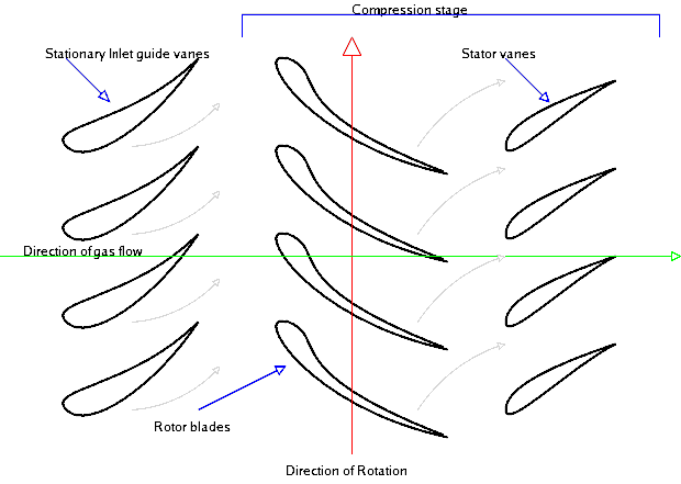
Because the pressure rises in the direction of flow through the compressor there is an acute risk of the boundary layers separating on the compressor blades as they encounter this adverse pressure gradient. When this happens the performance of the compressor drops dramatically and compressor is said to stall. For this reason the compression is spread over a large number of compressor stages such that the smaller incremental increases in pressure across each stage allow engineers to obtain a large overall pressure ratio without incurring stall. A stage consists of a row of rotating blades called the rotor and a row of stationary blades called the stator. Each of these rows may consist of between 30–100 distinct blades and there may be up to 20 stages between the air inlet and compressor outlet. The role of the rotor blades is to accelerate the incoming air in order to increase the kinetic energy of the fluid. Across the stators the fluid is then decelerated and as a consequence the fluid pressure is increased. As the pressure and density increase across each stage the overall flow velocity is kept relatively constant by reducing the height of the blades from stage to stage. Thus the compressor tapers down from inlet to outlet.
In an attempt to reduce the number of compressor stages for a more compact engine, a designer’s goal is to maximise the pressure ratio across each stage. The stage pressure ratio is given by the following expression,
Where is the stage isentropic efficiency, is the total (stagnation) temperature, the rotary speed of the compressor, the axial speed of the fluid, the coefficient of latent fusion at constant pressure, and and the angle of the rotor blade leading and trailing edge relative to the axial flow direction.
Diagram of an axial flow compressor
The pressure ratio across each stage can be maximised by increasing the rotary speed of the compressor , the angle through which the fluid is turned across the rotor blades and the axial speed of the fluid through the compressor. However there is a limit on the extent of these three parameters.
1. The blade tip speed and therefore is limited by stress considerations at the root. If the fan is assumed to be of constant cross-sectional area then the centrifugal stress at the root is given by,
Where is the tip speed, is the density of the blade, and the ratio is called the root-to-tip ratio of the blade. To prevent the blades from detaching from the hub and destroying the engine this root stress is not allowed to exceed a certain proof stress. It can be seen that the root stress is proportional to the square of the compressor rotational velocity and decreases as the blade length becomes shorter. Since the first compressor blades have the highest blade lengths they limit the maximum tip speed and therefore the efficiency of the compressor. It is therefore common to split the compressor into double or triple spool configurations such as a large fan, intermediate-pressure and high-pressure compressors that are rotating at three different speeds. In this manner the large diameter fan can rotate at lower speeds to satisfy the stress restrictions while the shorter blade high-pressure compressor may rotate at higher speeds.
However the rotational speed of the fan is typically constrained by more stringent stress considerations. In a turbofan engine the large diameter fan at the front of the engine acts as a single-stage compressor. In modern turbofan engines the fan divides the flow with most of the air going to the bypass duct to a propelling nozzle and only a small portion going into the core. The high root stresses caused by the long fan blades are often exacerbated by bird strikes. For mechanical reasons a lower limit of root-to-tip ratio of 0.35 is often employed. The flow impinging onto the fan is also at a very high Mach number since the cruising speed of civil aircraft is typically around M = 0.83. Supersonic flow inevitably terminates in a shock wave with a resulting increase in pressure and entropy over the compressor blades. Shock waves reduce the efficiency of the compressor blades since they disturb the flow over the profile that lead to boundary layer separation. Furthermore, these shock waves may cause unwanted vibrations of the fan blades that further reduce the efficiency of the compressor and increase noise. Therefore for reasons of efficiency, reducing noise and limiting the damage of bird strikes the tip speed of the fan is restricted, typically a relative Mach number of 1.6 is considered as the upper limit.
2. The axial speed has to be maximised to optimise the pressure ratio and reduce the frontal area of the engine. Similar to the argument given above the axial speed is typically limited by compressibility effects of supersonic flow. As the pressure, static temperature and therefore the speed of sound increases from stage to stage, the compressibility effects are worst in the first stages. For the first stage the air enters axially such that by adding the orthogonal velocity vectors and we get where V is the speed relative to the blade. In modern engines may be in the transonic region incurring quite large losses. In this respect twin-spool engines have the advantage that the lower-pressure compressor rotates at a lower speed, which reduces the compressibility problem.
3. The angle through which the fluid is turned across the rotor blades b is limited by the growth of the boundary layers. Compressor blades are aerofoils that function in the same manner as aeroplane wings. Therefore as the angle of attack or camber of aerofoil is increased to increase the rotation of the flow velocity vector, the adverse pressure gradient across the suction surface increases, until at some point the boundary layer separates. As the boundary layer separates the effective turning angle b is reduced such that the total pressure increase across the stage reduces.
The limits of , and all place limits on the maximum pressure ratio that can be achieved in an axial compressor. Typical examples are 350 m/s, = 200 m/s, 45°.
Compressor blades are typically quite thin and are constructed from lightweight metallic alloys such as aluminium and titanium. The compressor blades feature an aerofoil section as shown in the Figure below. The centrifugal forces that act on the airflow are balanced by high-pressure air towards the tip of the blade. In order to obtain this higher pressure towards the tip the blade must be twisted from root to tip in order to change the angle of incidence on the flow, and therefore control the pressure variation over the blade.
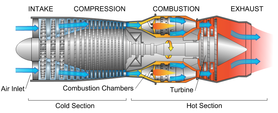
For aircraft jet propulsion there are in general four distinct designs: the turbojet, turbofan (or bypass engine), turboprop and turboshaft. This post will address the layout and design of the two most common engines used in modern aircraft, the turbojet and turbofan, and explain how their characteristics make each engine applicable for a specific task. Specifically, two important topics are addressed. The first is the multi-shaft engine with separate low-pressure and high-pressure spools and the second is the bypass engine, in which most of the air compressed by a fan bypasses the core combustor and turbine of the engine.
In general each engine is made up of four essential components: the compressor, combustor, turbine and nozzle as shown in Figure 1. The compressor raises the pressure of the incoming air before combustion, and the turbine, which extracts work from the hot pressurised combustion products, are at the heart of the engine. The role of the power turbine is not to provide thrust but to drive the compressor. The hot pressurised combustion products are expanded through a nozzle to produce thrust. In some military turbojet engines the exhaust velocity and therefore the thrust may be increased by “afterburning” in the exhaust duct.
Figure 1. Diagram of a typical gas turbine jet engine. Air is compressed by the fan blades as it enters the engine, and it is mixed and burned with fuel in the combustion section. The hot exhaust gases provide forward thrust and turn the turbines which drive the compressor fan blades.
1.1 The Turbojet
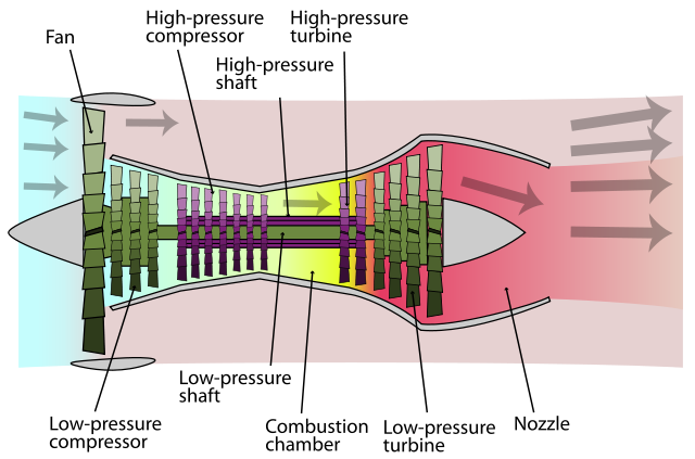
The turbojet is the earliest form of the jet engine as developed by Sir Frank Whittle and Hans von Ohain during WWII. It is no longer used for civil aircraft but predominantly used for high-velocity propulsion in military aircraft. Figure 1 shows a cross-sectional drawing of a typical turbojet engine and illustrates the typical layout of a turbojet engine with an axial compressor driven by an axial turbine, all on the same shaft. This assembly of shaft, compressor and turbine is oftentimes referred to as a “spool”. Newer engines typically have two or three spools such that the compression and expansion process in the compressor and turbine are spread over different parts. In this manner a low-pressure (LP) compressor and LP turbine are mounted on one shaft to form the LP spool. The LP shaft passes through the inside of the hollow high-pressure (HP) shaft on which are mounted the HP compressor and HP turbine. The compressor and turbine are split into separate parts to reduce centrifugal stresses in the compressor and turbine blades, and allow different parts of the compressor and turbine to be run at different speeds in order to optimise the running efficiency.
For sustained supersonic speeds a turbojet engine remains and attractive option for aircraft propulsion. The Rolls-Royce Olympus 593 is a two-shaft example that was used to propel the Concorde to twice the speed of sound.
1.2 A Note on Efficiency:
The propulsive or Froude efficiency of a jet engine is defined by the power output divided by the rate of change of kinetic energy of the air. The kinetic energy of the air represents the power input to the system. The power output is the product of force output i.e. the thrust and the resulting air speed . Although this is an approximation this equation summarises the essential terms that define aircraft propulsion. The force required to accelerate the fluid is given by the momentum equation,
Where is the mass flow rate of the air through the engine, is the velocity of the air entering and the velocity of the air leaving the engine. Thus there will be an equal and opposite force acting on the engine called the net thrust. The term is called the gross momentum thrust and is called the ram drag. Thus, for a turbojet the power output is,
So that,
For a fixed airspeed , can be increased by reducing . However decreasing decreases the thrust unless is increased. Thus, for civil aircraft when the economy is important is increased using high by-pass ratios of the turbofan, while for military engine where thrust is important low-by pass engines with large exit velocities are employed.
1.3 Optimisation of the Turbojet
When optimising the jet engine performance two parameters are typically considered: the specific thrust (ST) of the engine, and specific fuel consumption (SFC), the mass flow rate of fuel required to produce a unit of thrust. Generally speaking turbine designer have two thermodynamic variables to optimise these two entities: the compressor pressure ratio (R) and the turbine inlet temperature (TET). The effects of these two variables on SFC and ST will be considered in turn.
ST is strongly dependent on TET and TET should be maximised in order to keep the engine as small as possible for a specific amount of thrust. However, an increase in TET will incur a larger SFC at a constant R. On the other hand a gain in ST is generally more important than the penalty of higher SFC, especially at high flight speeds where a small engine is critical to minimise weight and drag.
Increasing R always causes a reduction in SFC and hence ensuring efficient compression stages is critical for an economic engine. For a fixed value of TET increasing R will initially result in more ST but will eventually cause ST to decrease again. Thus, there exists an optimum value of R, which is the role of the engineer to ascertain. Furthermore, the optimum pressure ratio for maximum ST increases with increasing TET.
This optimisation of R and TET can of course not be separated from the mechanical design of the engine. Driving up TET requires the use of much more expensive alloys and cooled turbine blades, which invariably lead to an increase in cost, mechanical complexity or otherwise a reduction in engine life. Increasing R will require larger compressors and turbines that incur weight, cost and mechanical complexity penalties.
Finally for different flight speeds and flight altitudes the performance of the turbojet will vary since the mass flow rate and momentum drag vary with density of the air and forward speed. Gross thrust decreases considerably with increasing altitude due to the decreasing ambient density and pressure, but specific thrust may increase due to a lower engine intake temperature. SFC however is reduced for increasing altitude, a result that was calculated by Frank Whittle as an engineering student, and led to his motivation for developing the jet engine.
2.1 The Turbofan
As revealed above the high exit velocity of turbojet engines does not allow high propulsive efficiencies required for civil aircraft. To raise the propulsive efficiency a bypass engine, often known as a turbofan engine, is used.
The core of the turbofan engine is essentially the same as the turbojet featuring a compressor, combustion chamber and power turbine as shown in Figure 2. However the engine features a second turbine that drives a large fan at the front of the engine. This fan delivers air to a bypass duct that channels air to the exhaust nozzle without passing through a combustion chamber. For this reason designers often refer to the cold flow in the bypass duct and hot flow through the core. Mixing the colder bypass air with the hot exhaust gases from the core results in higher propulsive efficiencies and lower noise levels. Early bypass engines typically had bypass ratios (the mass flow rate of bypass air divided by the mass flow rate of air going through the core) of around 0.3 to 1.5. The arrangements for modern airliners are High-Bypass-Ratio (HBR) engines with a bypass ratio of 5 or even more. In the Rolls Royce RB211 and Trent families the fan is driven at low speed by one turbine, and two internal compressors driven by another two separate turbines to give a triple spool engine.
Figure 2. Schematic Diagram of Turbofan Engine
2.2 Optimisation of the Turbofan
For turbofan design engineers have four major variables to consider: the bypass ratio (BR), overall pressure ratio (OR), fan pressure ratio (FR) and TET. Similar to the turbojet high TET is required for increased thrust. As the FR is increased the thrust contributed by the cold flow is increased while that of the hot flow decreases since more power is required to drive the fan. There is an optimum value of FR for which the total thrust is a maximum. In actual fact the optimum value of FR when is a maximum automatically produces minimum SFC if OR and BR are fixed.
The propulsive efficiency rises and the SFC falls as BR is increased. For laung-haul subsonic aircraft SFC is important to reduce cost. For these engines BR is typically between 4 and 6 and OP and TET are high. Thrust is more important for military aircraft such that BR is typically reduced to 0.5 to 1. BR significantly affects the engine efficiency, appearance, size and weight of the engine. As the weight of the engine increases less payload can be added to the aircraft such that the airlines revenue falls. Second, increasing the lift produced by the wings to carry bigger engines automatically induces more drag. Finally, for practical reasons BR > 10 are not practical with current technology since it would be necessary to install a gear box between the driving power turbine and fan to allow the turbine to run faster. Such a design would most certainly require considerable development time and would probably incur a weight penalty that outweighs the benefits of increasing the BR. Thus optimisation of the engine cannot only be considered in terms of thermodynamic parameters and aircraft manufacturers ultimately decide which engine to install based on what design gives airlines the highest financial yield.
In a typical turbofan jet engine the oncoming airflow is compressed throughout a series of compressor stages, mixed with a fuel (typically kerosene) and combusted, drastically increasing pressure and temperature, and then expanded through a nozzle to provide thrust towards the rear of the aircraft. By accelerating the fluid towards aft, Newton’s Third Law implies that this impulse must be reacted by an equal and opposite force in the opposite direction, thus propelling the aircraft forward. However, modern jet engines are also capable of producing thrust in the opposing direction. How is this possible without completely changing the direction of airflow from the exhaust to the intake which would seriously damage various engine components?
Diagram of a typical gas turbine jet engine. Air is compressed by the fan blades as it enters the engine, and it is mixed and burned with fuel in the combustion section. The hot exhaust gases provide forward thrust and turn the turbines which drive the compressor fan blades.
Thrust reversal is achieved by momentarily diverting the hot exhaust gases towards the front of the aircraft or changing the propeller/compressor pitch so that the thrust produced is directed forward. Thus thrust will act against the forward direction of travel and provide a means of deceleration. Thrust reversal is used in some flight scenarios in order to,
Alleviate the stress and reduce wear on the brakes or to enable shorter landing distances. Reverse thrust can reduce the braking distance by a third or more!
Momentarily increase the braking force during emergencies or just after touchdown when the aircraft is still traveling at a high velocity and the residual aerodynamic lift is significant. Lift reduces the normal reaction force with the ground and therefore limits friction and grip on the tyres.
Rapid deceleration in flight to enable quick changes of speed. Most aircraft cannot operate thrust reversal in flight and the majority that can are propeller-driven.
Helping to push an aircraft back from a gate. A maneuver called “powerback”.
Almost everyone who has sat in a row near the wings will have heard reverse thrust in action before. Next time you land wait for the sudden high-pitched increase in engine noise just after touchdown.
The method to achieve thrust reversal varies greatly between the different types of engines:
Since the 1930s propeller-driven aircraft generate reverse thrust by changing the angle of attack of their controllable pitch propellers:
Older reciprocating engines and modern turboprop engines both have the ability to set the propeller angle to “flat pitch”. As a result the propellor airfoils produce no forward or reverse thrust, but large amounts of drag instead. This allows the engine speed to be kept at a constant speed while descending.
The classic approach is to pitch the propeller blades to a negative angle of attack in order to direct the thrust forward.
In jet engines thrust reversal is not accomplished by running the engine in reverse but by diverting the high-velocity exhaust jet blast to the front of the engines. This can be achieved in different ways:
The target-type thrust reverser: After the combustion chamber, reverser blades angle outward in order to prematurely redirect the high-speed jet radially outwards and towards the front of the engine. This construction generally gives the appearance of flower petals.
The clamshell type: Two reverser buckets are hinged at the aft of the engine, and when deployed, intrude into the exhaust of the engine. In this manner the jet blast is captured and re-oriented towards the front.
In a turbofan engine some of the air intake is not passed through the main part of the engine, but redirected along an outside channel without being combusted. This bypass duct is aptly named “cold flow” and this arrangement is used to save fuel and reduce engine noise. Furthermore, the bypass flow can also be used to channel air radially outwards and forwards to provide thrust reversal.
The three different types of thrust mechanisms explained above [1].
Youtube has some great videos showing thrust reversal in action.
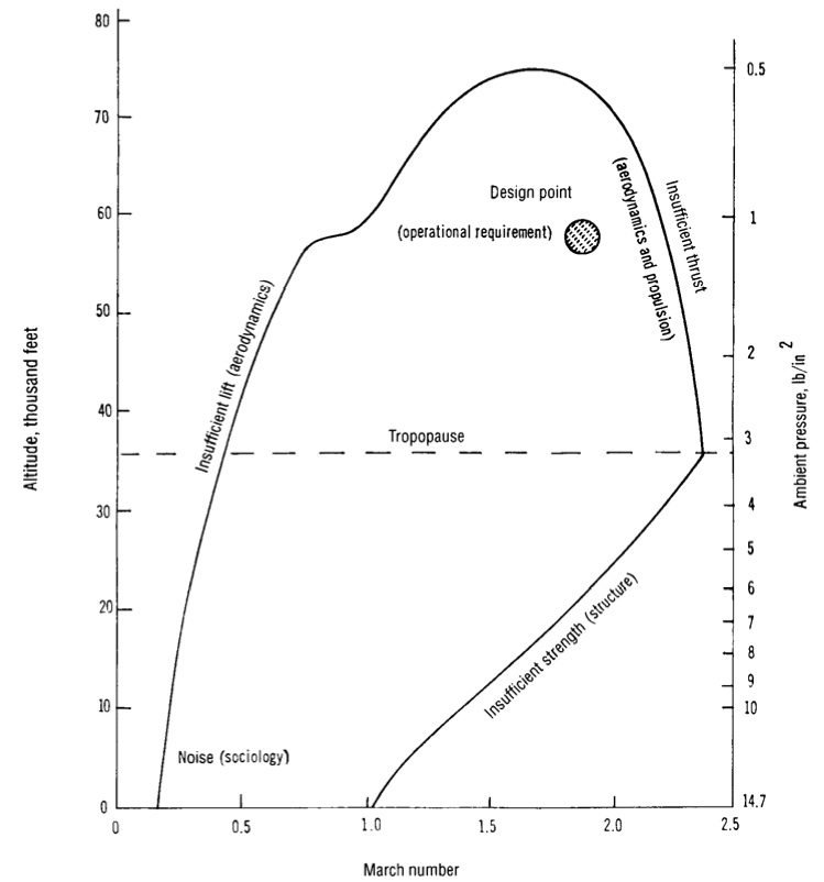
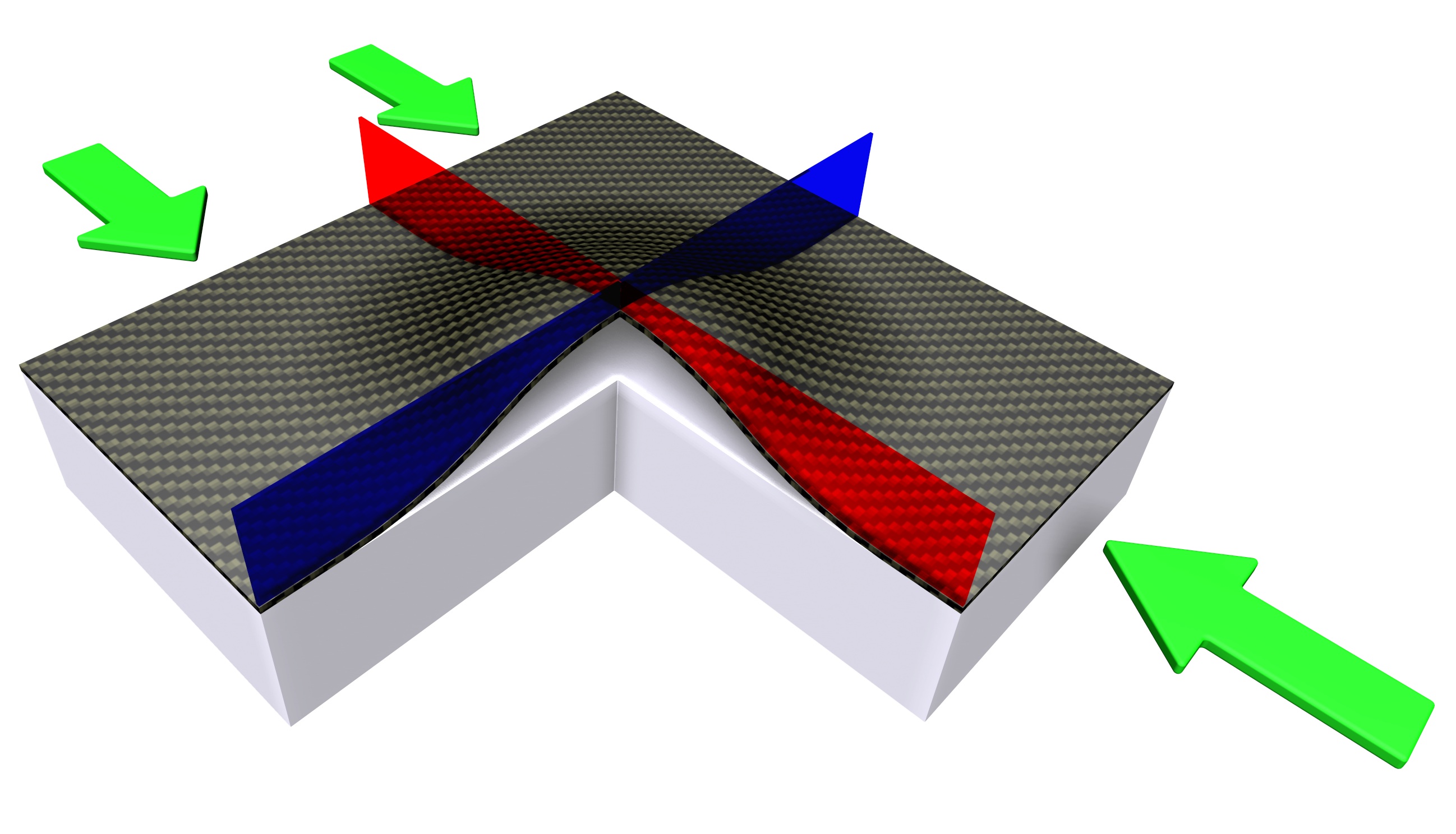
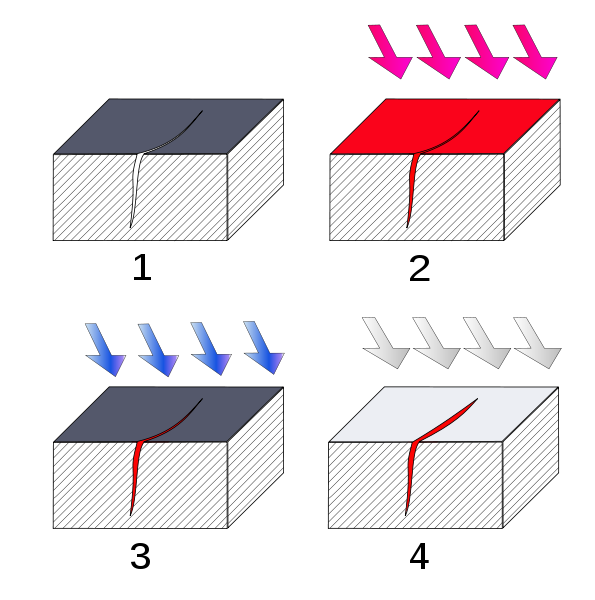
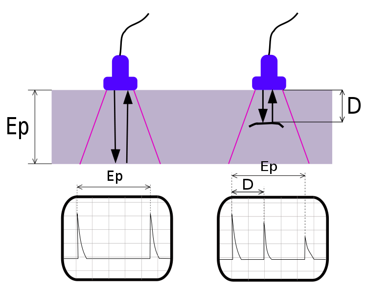
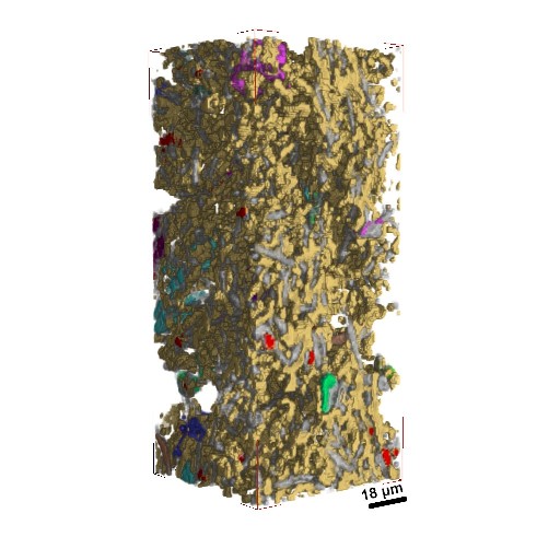
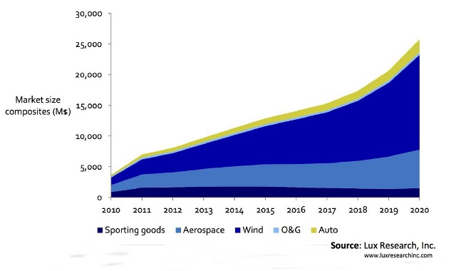
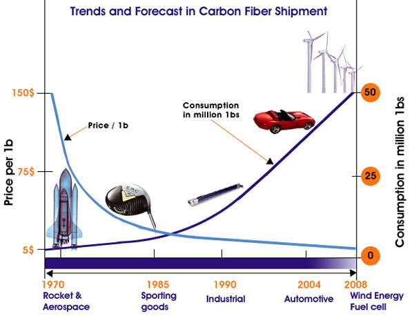
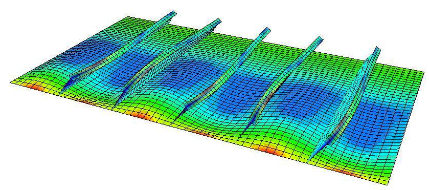
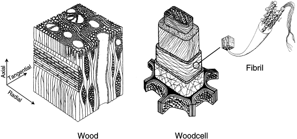
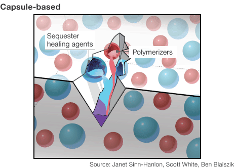
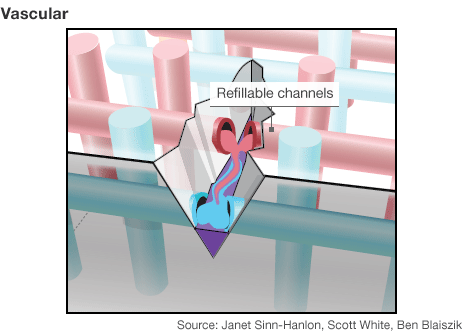
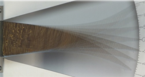
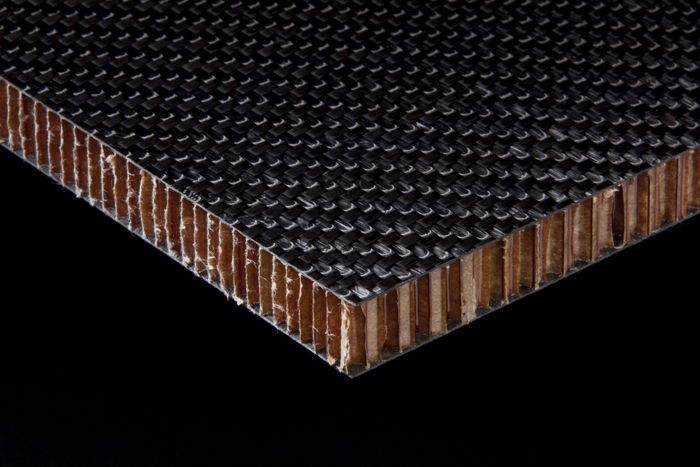
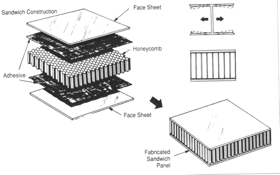
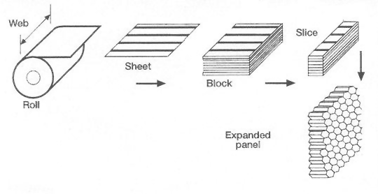
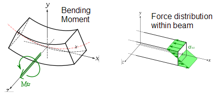
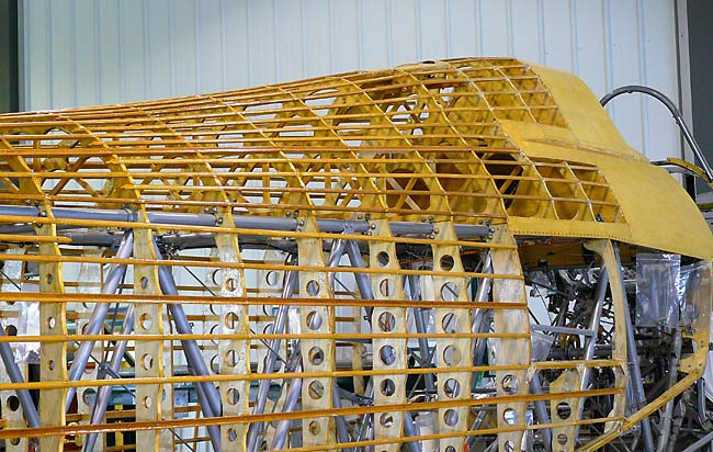
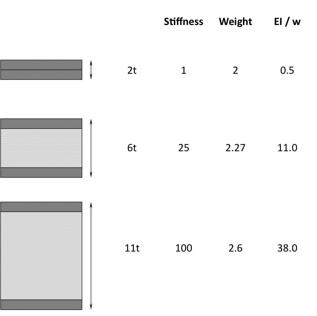
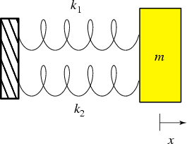
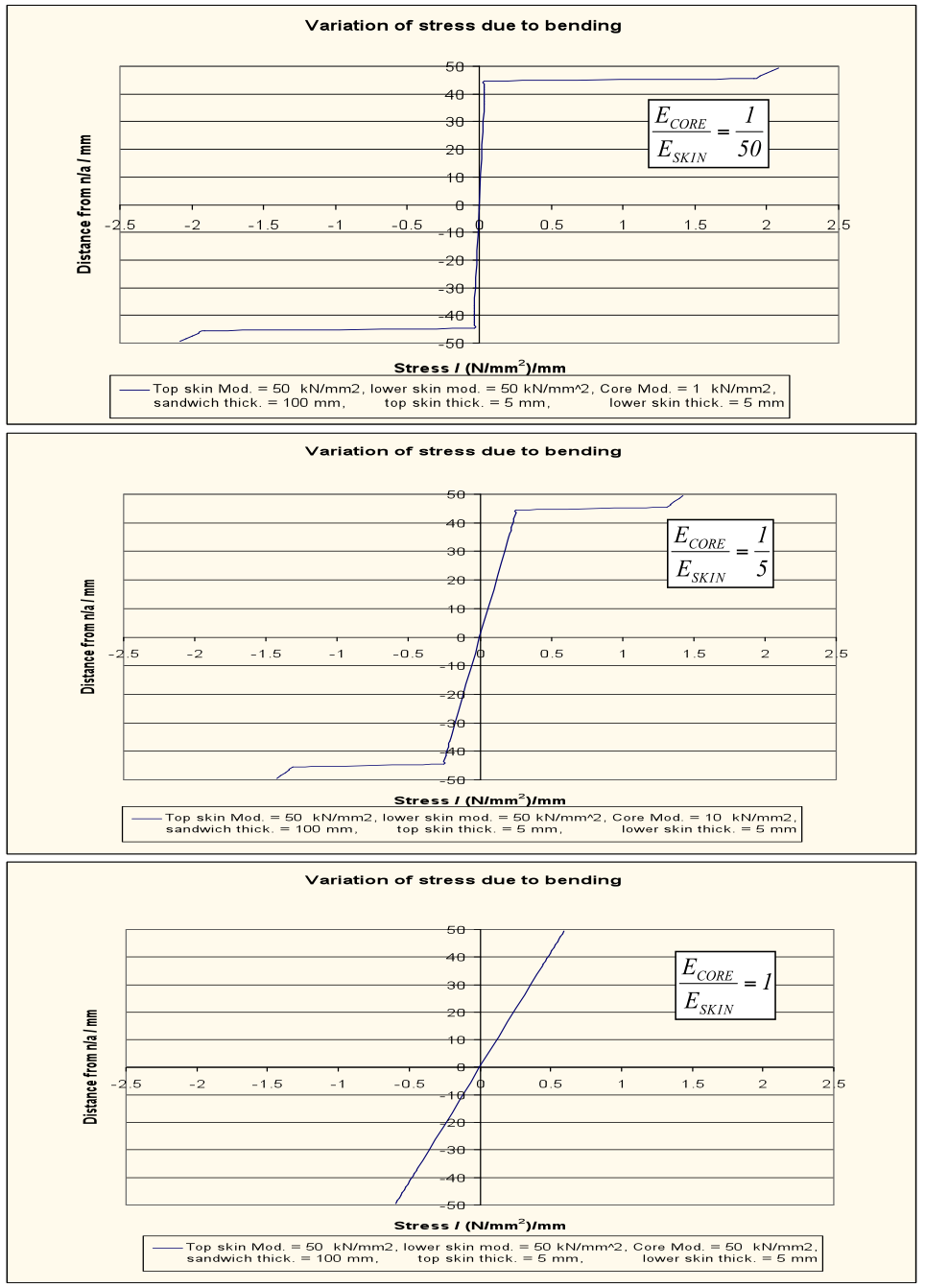
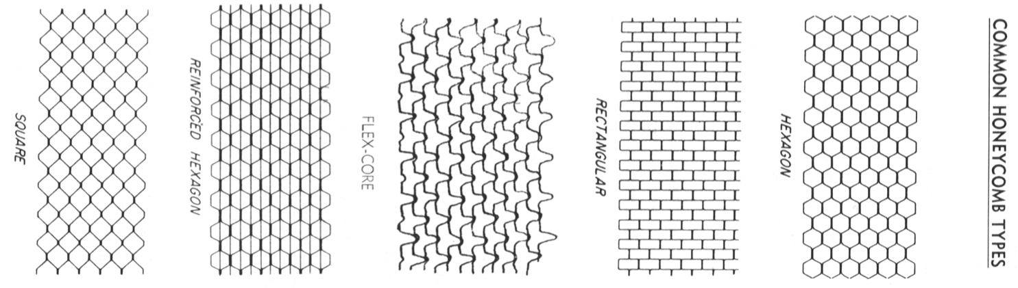
.")

![Fig. 1. Triple Stage Turbine [2]](https://rgroh.com/wp-content/uploads/2013/04/triple-stage-turbine.jpg)
![Fig. 2. Velocity triangles for turbine stage [2]](https://rgroh.com/wp-content/uploads/2013/04/fig9VelTrianglesTurbine_web.jpg)
![Fig. 3. The microstructure of the three different turbine blades [4].](https://rgroh.com/wp-content/uploads/2013/04/img014.jpg)