Category: Publications

  • Model for kirigami buckling

    Model for kirigami buckling

    Kirigami is the sister of the more well-known origami. While origami focuses on creating art out of folding paper, kirigami extends this to allow for cuts to be introduced. Both origami and kirigami have been researched extensively over the last decade to explore potential applications in structural engineering.

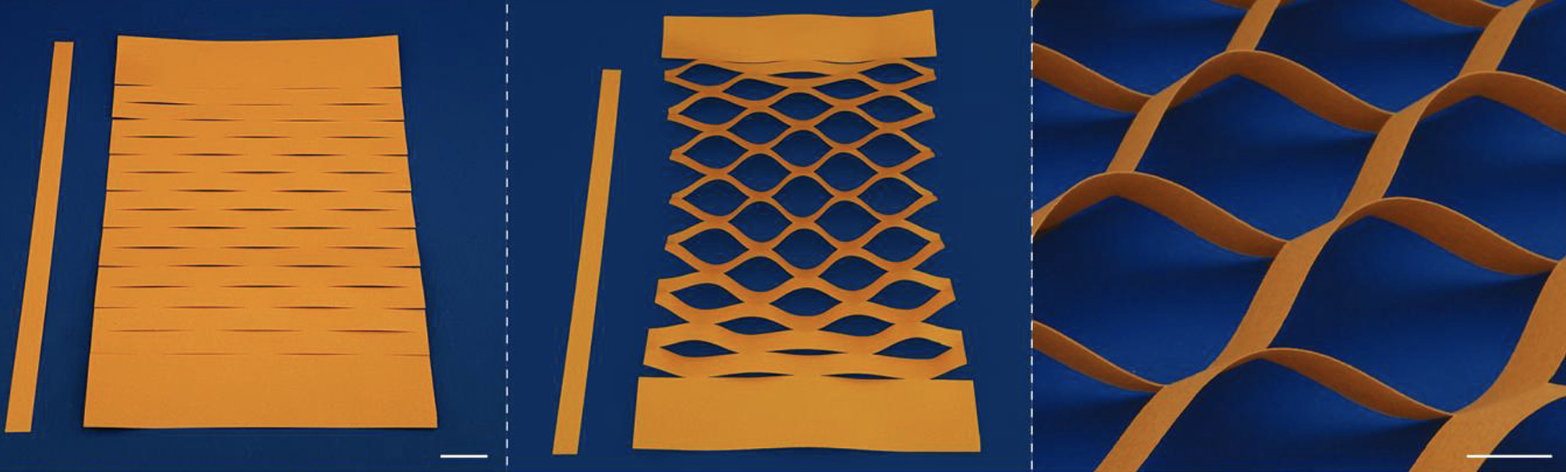
    For example, when a parallel matrix of cuts is introduced into a sheet of paper and that sheet is then tensioned, the cells between the cuts buckle out-of-the-plane to form a pattern. This effect is currently being used for expandable packaging but also to create lightweight tension springs for space applications.

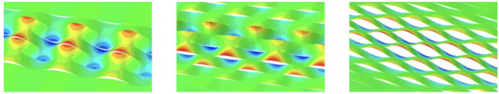
    What is interesting is that depending on the ratio of cut length to vertical and horizontal cut spacing, different patterns can form. The cells either buckling anti-symmetrically, symmetrically or into a mixture of these two motifs (co-existence). These three behaviours lead to significantly varying tensional stiffness, which means that design approaches are needed to predict the buckling onset and stiffness correctly.

    left: symmetric mode; right: anti-symmetric mode; middle: co-existence

    To date, the three regimes have largely been explored using computational methods, e.g. finite element analysis. These methods are very accurate but tend to be slower than analytical methods and require designers to have access to sophisticated modelling software. In a recent publication, one of my PhD students (Yuwen Du) and I have introduced an analytical model that correctly predicts buckling loads as well as the buckling modes into the three possible configurations.

    With such a model it is now possible to rapidly design with this particular kirigami structure. In addition, the model has allowed us to delineate the energetic contributions that force the kirigami sheet to buckle into the anti-symmetric or the symmetric mode.

  • Gust load alleviation for aircraft wings

    Gust load alleviation for aircraft wings

    Aircraft wings are designed for the worst-case scenario encountered during a service lifetime. Generally, this is a severe gust that occurs only a handful of times but produces significant bending stresses at the wing root to require substantial reinforcement. Because the aircraft spends the majority of its lifetime not experiencing such a rare, extreme load case the wing is over-designed for much of its service life.

    The additional reinforcement and mass required to sustain these rare load cases unnecessarily increases fuel burn during standard operation (99.9% of the time).

    What if this extreme load case could therefore be removed from the aircraft’s life cycle?

    For example, by deploying a spoiler or tab into the airflow on the top wing surface to disrupt the boundary layer, detach the flow, and thereby dump lift and reduce bending moments at the root of the wing.

    Such a device is possible, but usually requires the integration of an active control system with sensors and actuators that also add weight and complexity to the structure and aircraft system. A more elegant solution is to use a passive device. For example, a structure that deforms as the wing bends during a gust and then triggers the spoiler to pop-out of the top wing surface. In a way, this would represent a “reflex” of the wing to protect itself from severe loading.

    In previous work, we (PhD student Ed Wheatcroft and Bristol colleagues Mark Schenk, Alberto Pirrera and I) designed such a device (1, 2) and tested its performance in a wind tunnel (see above image). These wind tunnel experiments proved the concept that a deploying leading-edge spoiler (albeit using an actuator in this proof of concept) could effectively reduce the lift produced by the airfoil.

    In our latest publication, the effectiveness of the spoiler is demonstrated on an aircraft-level study in collaboration with Airbus UK. To do this, an idealised full aircraft model was simulated and subjected to a number of different flight load cases, with the lift-reduction effect of the spoiler hard-wired into the simulation. The results demonstrated that the spoiler is capable of reducing the sizing wing root bending moment by up to 17% for the particular airframe considered.

    Following these promising results, the next steps are to integrate a spoiler into a flexible wing model that can then be tested live in a wind tunnel.

  • Multi-rotor wind turbines

    Multi-rotor wind turbines

    A PhD student I am co-supervising (Abdirahman Sheik Hassan) has just published his first paper—a review on multi-rotor wind turbines.

    To extract more and more energy from the wind, turbine blades are getting longer and longer. This scaling places significant challenges on the materials, manufacturing, testing, transportation, operation, and maintenance of the blades. With blades exceeding 100 m in length, glass-reinforced composites are increasingly being replaced with stiffer carbon fibre; the quality of resin infusion during manufacturing is increasingly difficult; and the transportation to the final site along roads is a major logistics operation.

    One possible solution out of this bottleneck is to locate multiple smaller rotors on a single supporting frame, a so-called multi-rotor system. Not only would this approach remove many of the challenges listed above around manufacturing and transportation, but it would theoretically allow the use of more sustainable bio-based composites whose inferior mechanical properties make them unsuitable for longer blades. In addition, analytical scaling arguments suggest that the cost of energy from multi-rotors decreases favourably with the number of rotors employed.

    Our review paper summarises the literature on multi-rotors from the past decades including aerodynamics, materials, structures, design, control, sustainability, reliability, and
    maintenance. The paper also highlights open questions around the environmental impact benefits of multi-rotors, the characterisation of rotor–rotor inter-
    action effects, and the investigation of aerodynamic noise, amongst others.

  • Prediction of dimple initiation site in shells using digital image correlation

    Prediction of dimple initiation site in shells using digital image correlation

    I have just published a new paper in the Proceedings of the Royal Society A with collaborators at IIT Hyderabad (India).

    Thin-walled cylinders are used in various engineering applications ranging from fuselages in aircraft to fuel tanks in launch vehicle stages. When thin-walled cylinders are compressed, they are susceptible to buckling and this occurs at loads well below what is suggested by analysis. As a result, cylinders are designed with very conservative safety factors.

    One way to improve the design process is to devise a non-destructive testing framework that can predict when a manufactured cylinder will buckle, which would then provide information on potential remedial measures. Such a methodology has recently been developed, where a cylinder is probed laterally from the side to measure its resistance to indentation, but the method is very dependent on the location of probing.

    Buckling of cylinders is a local event, where a single dimple initiates a dynamic buckling sequence. Probing should occur at the weakest spot where the dimple initiates. However, this site is not known a priori as it depends on imperfections in manufacturing and loading.

    Our paper showed that the dimple initiation site can be predicted from deformation measurements (using digital image correlation) before buckling occurs. The measured deformations are used to compute a bending energy measure which successfully reveals the presence of a developing dimple at approximately 60% of the critical buckling load.

    This information can help to determine where to probe the cylinder to determine the buckling load in a non-destructive manner, i.e. without ever pushing the cylinder to the buckling point.